{{ secondMenu.name }}


Install the OS on FC/FCoE external storage when HCI is deployed on the diskless server.
Precautions
1. Only FC storage is supported for SAN Boot.
2. After installation and deployment, record the required information for configuration to ensure that HCI can boot normally from the external storage.
3. Nodes using SAN Boot cannot be added to a virtual storage pool.
4. Only x86 nodes are supported for SAN Boot.
Prerequisites
1. To enable SAN Boot, install the HBA card in advance, and ensure that the BIOS can properly identify the corresponding storage device.
2. The LUN on the FC storage (required disk space: At least 128 GB) must be mapped to the server to ensure that the mapped disk information can be identified during installation and deployment, thereby allowing normal installation.
Steps
1. Prepare a new diskless server.
2. Insert the CNA NIC or HBA card.
3. Connect the server to the FC SAN network through the CNA NIC or the HBA card.
4. Refer to section ISO Installation to mount the pre-downloaded image file to the server's virtual CD/DVD drive.
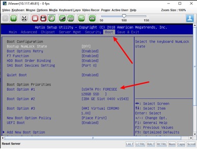
5. Take the example of an Inspur server: To access the FC storage configuration by clicking Ctrl+Q after installation is complete, restart the server. During the startup process, press the Delete key to enter the setup page, and configure as follows.
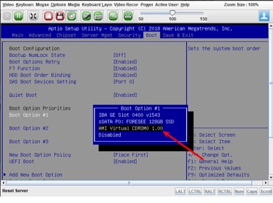
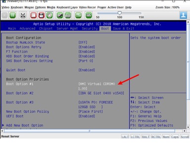
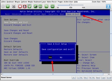
6. Click the BOOT tab, click Boot Option #1 in the Boot Option Priorities section, and select AMI Virtual CDROM0 1.00 in the pop-up window. Click the Save & Exit tab, click Save Changes and Exit in the Save Options section, and click Yes in the Save & Exit Setup pop-up window.
7. After the configuration is complete, start the server to enter the installation page.
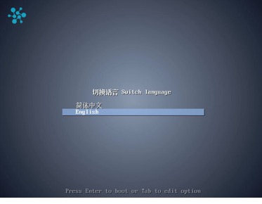
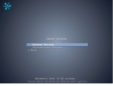
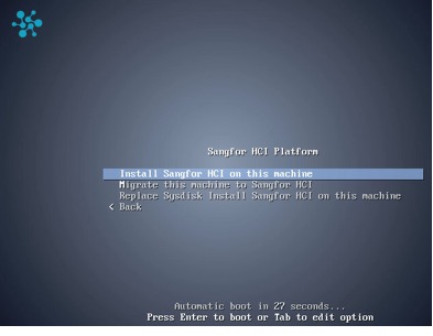
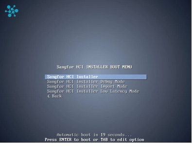
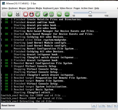
8. Select Install Sangfor HCI on this machine on the page, select Sangfor HCI Installer, and wait for the installation to execute.
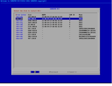
9. Select the FC storage as the installation device. The information related to FC storage such as WWPN and LUN ID will be displayed. Disks displayed as - in the WWPN and LUN ID sections are local disks.
After the corresponding LUN is selected, the Whether to Enable Offline Protection for System Disk pop-up window will appear.
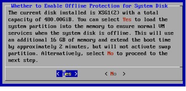
Offline protection for system disk refers to the mechanism where, during the system startup, some partitions are loaded into RAM before services are started. In this way, when the external storage is offline, the frontend page will remain accessible for login, and an alert banner will be displayed, ensuring that existing VM services remain running properly.
![]()
1. After offline protection is enabled for a system disk, if the system disk size is less than 240 GB, the used memory space will increase by 14 GB.
If the system disk size is 240 GB or larger, the used memory space will increase by 16 GB.
2. Upgrade restrictions: For deployed nodes with system disk offline protection enabled, in-place active upgrades, rolling upgrades, and offline upgrades are supported. In-place active upgrades will not restart nodes.
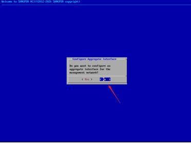
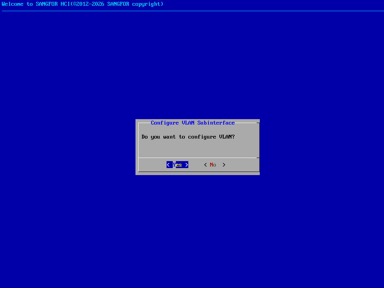
10. After system installation is complete, the Configure Aggregate Interface pop-up window will appear. You can choose to configure an aggregate interface for the management interface. Click Yes to enter the aggregate interface configuration page, or click No to enter the single-NIC configuration page.
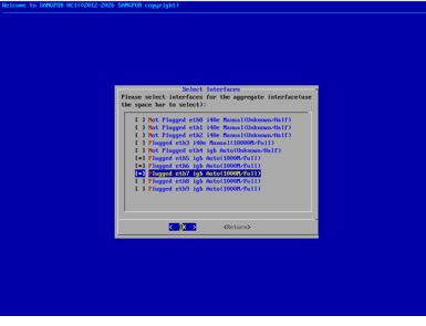
NIC aggregation:
Select the interfaces for the aggregate interface in the Select Interfaces pop-up window.
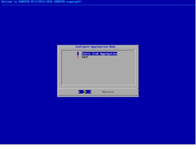
Configure the aggregation mode.
Configure the VLAN.
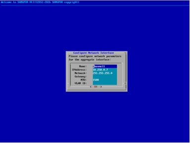
Configure Name, IPAddress, Netmask, Gateway, MTU, and VLAN ID in the Configure Network Interface pop-up window.
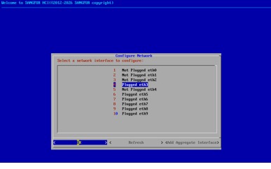
Single-NIC configuration:
Select a network interface in the Configure Network pop-up window and click OK.
Configure IPAddress, Netmask, and Gateway for the selected network interface.
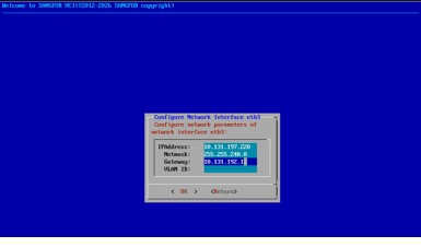
Choose whether to configure VLAN.
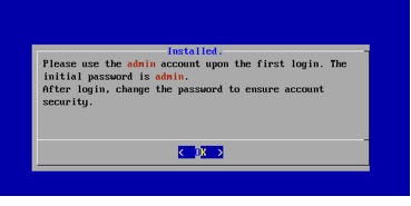
11. The default account password is admin. Upon first login, the password must be changed to ensure account security.
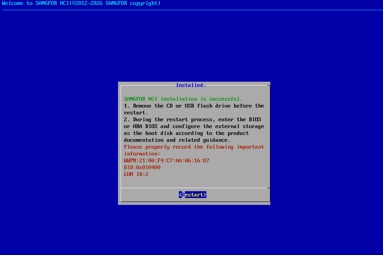
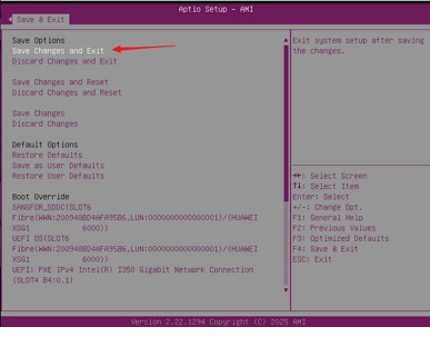
12. After installation is complete, the WWPN, DID, and LUN ID of the FC LUN where the system is located will be displayed in the Installed pop-up window. Click Restart to restart the device. During the device restart process, enter the BIOS and configure the server to start from the FC LUN.
13. After restart, the BIOS configuration differs between Intel 6 series servers and non‑Intel 6 series servers. For Intel 6 series servers, restart the device after the configuration is complete, and step 14 is not required.
(1) BIOS configuration for Intel 6 series servers:
Configuration options differ among different HBA card models and must be fixed accordingly.
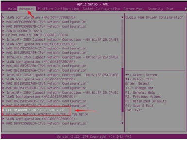
HPE Card
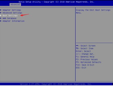
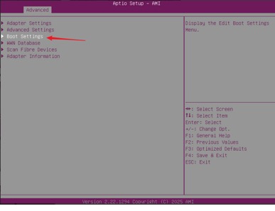
Log in to BIOS and locate the corresponding HPE card on the Advanced tab.
Click Adapter Settings on the Advanced tab.
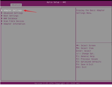
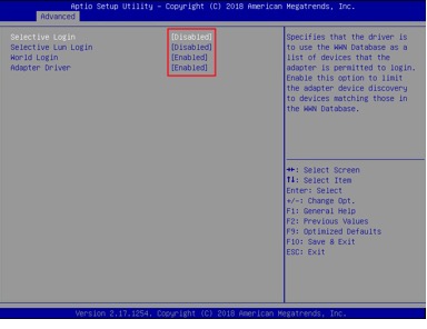
Change the configuration as shown in the figure below.
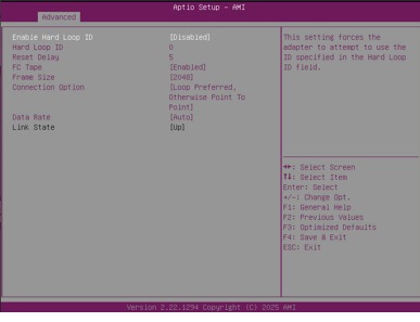
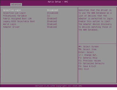
Change the configuration for Boot Settings as shown in the figure below.
Boot configuration:
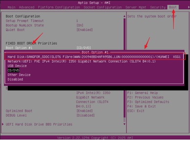
Click the Boot tab, select the corresponding FC device as BOOT OPTION #1. (If the device does not appear on the Boot tab after the above configuration is complete, save the configuration, restart, and log in to BIOS again. The device will then appear on the Boot tab.)
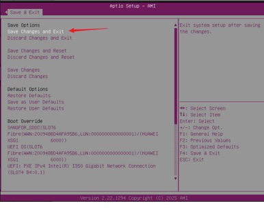
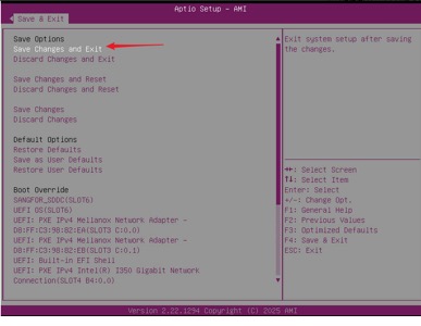
Click the Save & Exit tab, click Save Changes and Exit in the Save Options section, click Yes in the Save & Exit Setup pop-up window, and then start the server.
QLogic Card
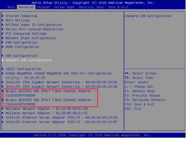
Log in to BIOS and locate the corresponding QLogic card.
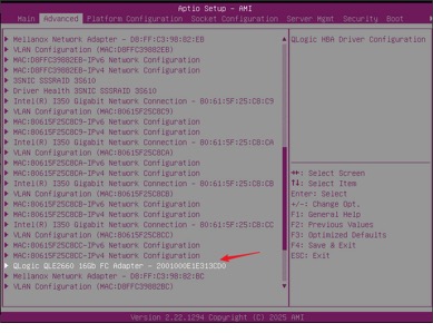
Click Fibre Channel Target Configuration on the Advanced tab.
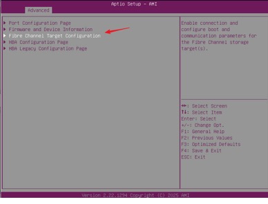
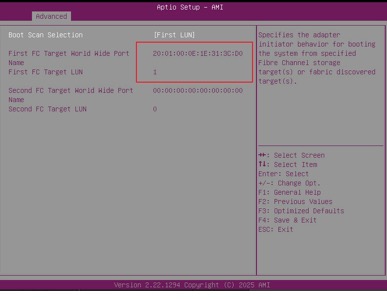
The WWPN and LUN ID in the FC target configuration must match the information displayed before the restart in step 12.
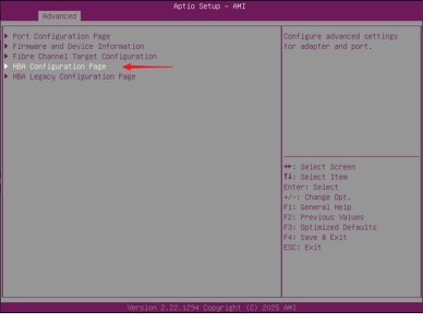
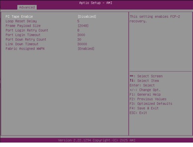
Click HBA Configuration Page on the Advanced tab.
Change the configuration as shown in the figure below.
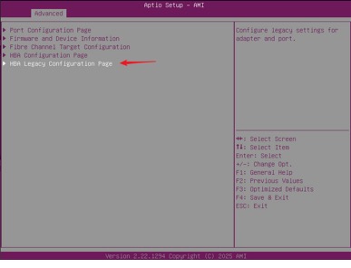
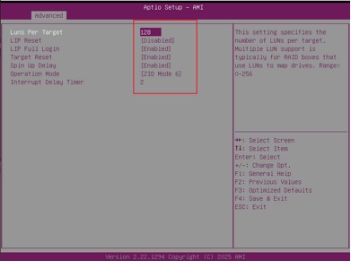
Click HBA Legacy Configuration Page on the Advanced tab.
Change the configuration as shown in the figure below.
After the above configuration is complete, save the settings and restart. During the restart, the server will load the latest configuration and identify the storage device. Follow the prompts to go to the BIOS page.
Click the Boot tab on the BIOS page and set the corresponding FC device as Boot Option #1.
Click the Save & Exit tab, click Save Changes and Exit in the Save Options section, click Yes in the Save & Exit Setup pop-up window, and then start the server.
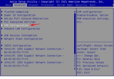
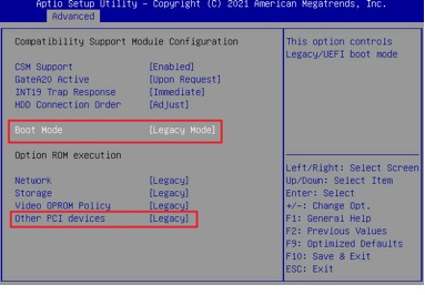
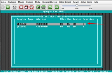
(2) BIOS configuration for non‑Intel 6 series servers: FC must be configured for non‑Intel 6 series servers to map the corresponding device, ensuring that the correct boot device can be selected in the boot configuration. Step 18 is required. During the restart, press Ctrl+Q according to the prompt to go to the target page.
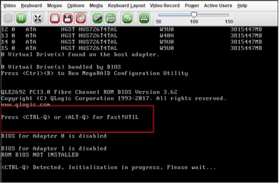
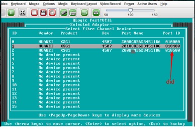
Select the corresponding adapter (if unsure which one to select, click each adapter one by one to view the corresponding device configuration).
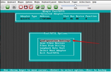
Click Configuration Settings in the Fast!UTIL Options pop-up window.
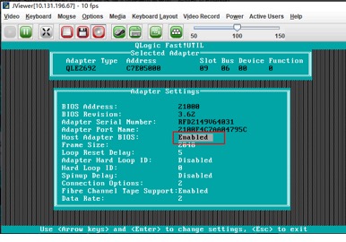
The Adapter Settings pop-up window appears, and set Host Adapter BIOS to Enabled.
Press the Esc key to exit the Adapter Settings pop-up window. Select the corresponding HBA card. In the Configuration Settings pop-up window, select Selectable Boot Settings and press the Enter key.

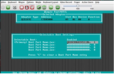
Set Selectable Boot to Enabled in the Selectable Boot Settings pop-up window.
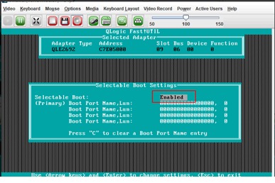
Select the corresponding LUN.
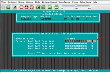
The corresponding LUN information is the prompt displayed during the restart in step 16 . After selection, press the Enter key to confirm.
After the configuration is complete, keep pressing the Esc key until the Configuration settings modified pop-up window is displayed. Click Save changes and press the Esc key to exit.
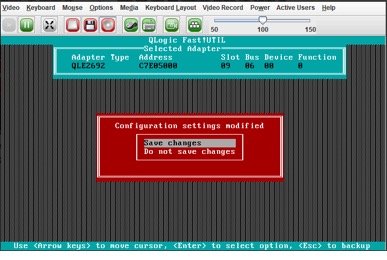
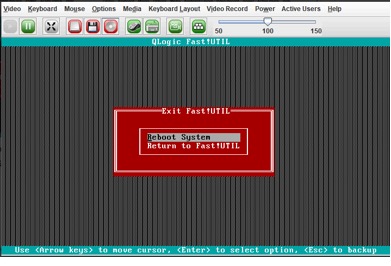
Click Reboot System in the Exit Fast!UTIL pop-up window.
14. BIOS adjustment: Change to FC LUN Boot.
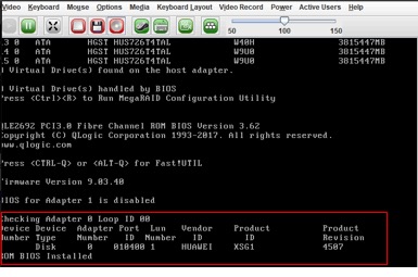
During the startup, the corresponding adapter information will be displayed.
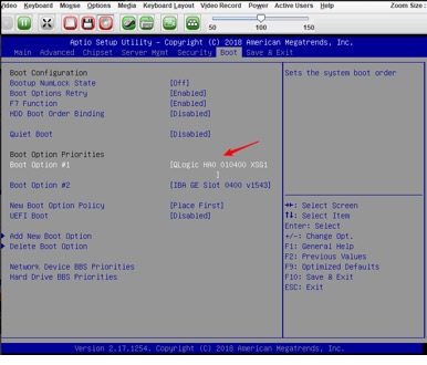
Press the Delete key to go to the Boot tab.
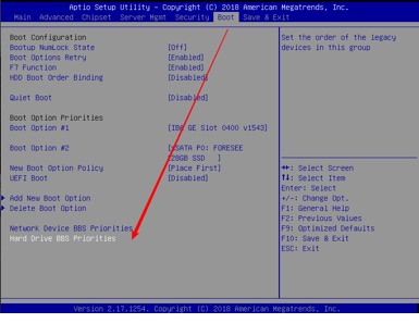
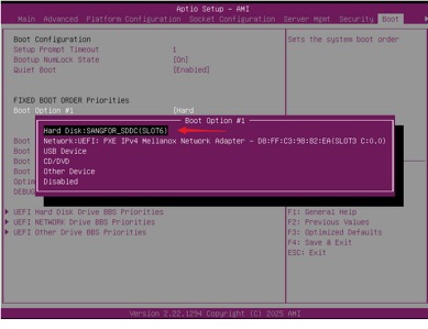
Click Hard Drive BBS Priorities in the Boot Option Priorities section and move the FC configuration to Boot Option #1.
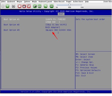
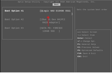
Press the Esc key to return to the previous page, then set Boot Option #1 to QLogic HA 0.
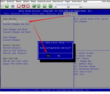
Click the Save & Exit tab, click Save Changes and Exit in the Save Options section, click Yes in the Save & Exit Setup pop-up window, and wait for the restart.
15. After the BIOS configuration is complete, the server starts. Log in to the HCI web console using the URL (https://configured IP address). Go to Nodes > System Disks to check which nodes are in SAN Boot mode in the Type column.

Log in to the HCI web console using the URL (https://configured IP address).
1. Go to the HCI installation page via direct console or BMC system, etc.
2. Select Sangfor HCI Installer.
3. After the installation is complete, go to BIOS according to the prompt before the restart.
4. Configure the boot disk in the BIOS (Detailed information will be supplemented later).
5. After the BIOS configuration is complete, restart or continue the startup process to start the HCI system normally.

 {{ $t('index.defaultHeader.chromeBrowserTip') }}