{{ secondMenu.name }}


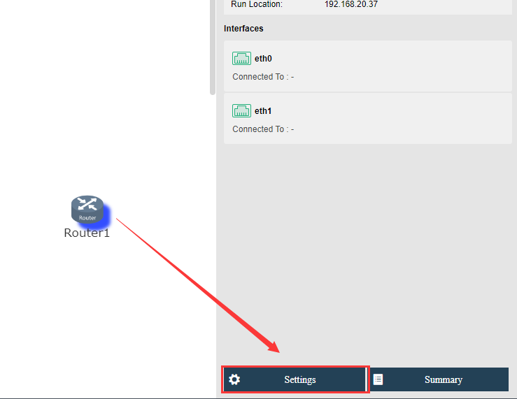
You can configure a virtual router by clicking Settings button to enter the Settings page. On that page, you can configure interface and VLAN subinterface, static route, NAT, access control policy, DHCP, DNS and high availability (HA).
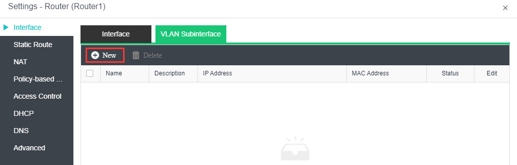
On the Interface tab, you can configure the router's network interface and the corresponding VLAN subinterface. 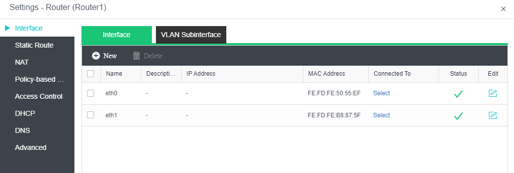
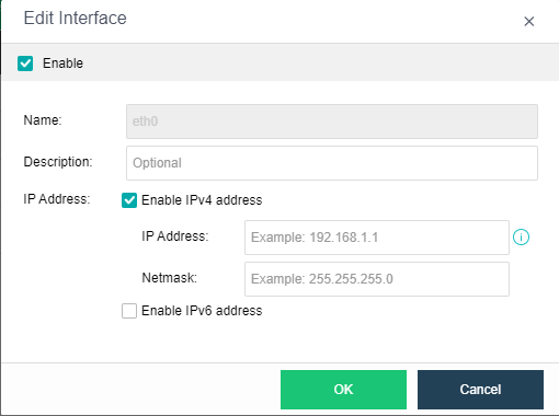
To add interface(s), click New and specify the number of interfaces that you want to add
Support to enable Ipv4 and Ipv6 address in the interface.
On the Route tab, you can configure a static route, or multiple static routes at a time. Static route works when the router needs to send packets to various subnets. You may add one static route at a time or multiple static routes at a time.
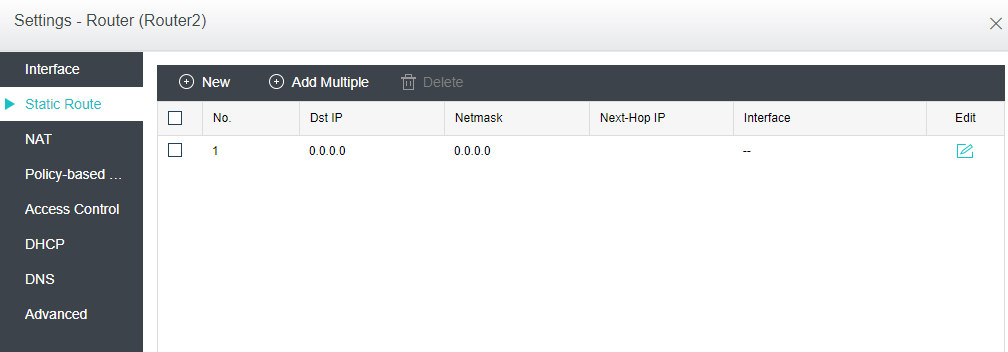
To add a static route, click Add Static Route and configure related fields on the following page: 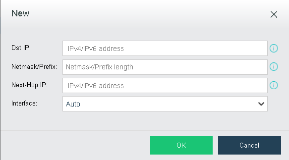
Dst IP: Specifies the destination Ipv4 or Ipv6 address.
Netmask: Specifies netmask corresponding to the destination IP address.
Next-Hop IP: Specifies the next-hop Ipv4 or Ipv6 address.
Interface: Specifies the interface through which data is forwarded.
To add multiple static routes, click Add Multiple to enter the following page: 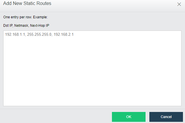
One static route per row. Example: destination IP address, netmask, next-hop IP address.
On the NAT tab, you can configure SNAT and DNAT rules. SNAT is used to translate source IP address of a data packet, while DNAT is used to translate destination IP address of a data packet and commonly used to publish an internal service on a publicly accessible IP address. 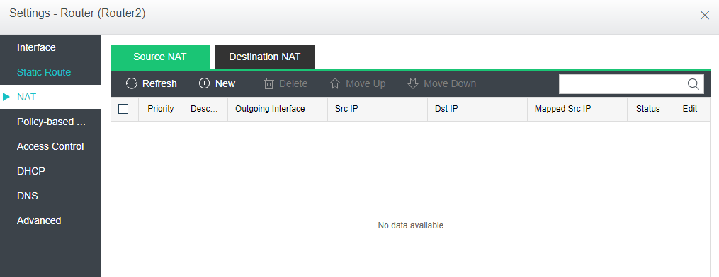
To add a source NAT rule, click Add on the Source NAT tab and configure the fields on the following page: 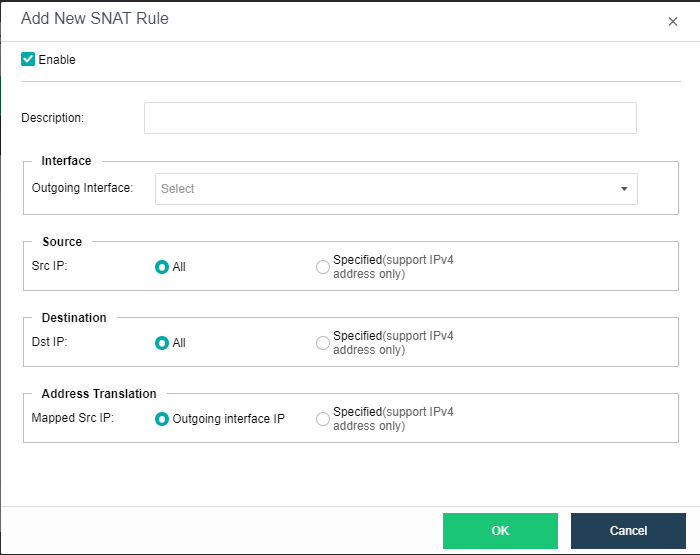
Enabled: Select this option to enable the SNAT rule.
Description: Specifies description for the SNAT rule.
Interface: Specifies outgoing interface through which data is forwarded.
Source: Specifies source IP address. Options are All and Specified. If Specified is selected, only the IP addresses within the specified IP range will be translated
Destination: Specifies destination IP address. Options are All and Specified. If Specified is selected, only the source IP addresses of the packets routed to the specified destination IPaddress will be translated.
Address Translation: Specifies mapped source IP address. If Outgoing interface IP is selected, source IP address will be translated to the IP address of specified outgoing interface. If Specified is selected, source IP address will be translated to the specified IP address.
To add a DNAT rule, click Add on the Destination NAT tab, as shown below: 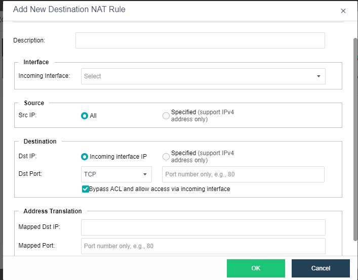
Enabled: Select this option to enable the DNAT rule.
Description: Specifies description for the DNAT rule.
Interface: Specifies the incoming interface through which inbound traffic flows into intranet.
Source: Specifies source IP address.
Destination: Specifies destination IP address and port. Destination IP address can be incoming interface address or a specified IP address. If Incoming interface IP is selected, the destination IP address will be translated to specified IP address only when the dst address is matching with the specified incoming interface address. To translate a destination port, you need to specify protocol, port number and mapped port. To bypass ACL and allow access via incoming interface, select the option Bypass ACL and allow access via incoming interface.
Address Translation: Specifies mapped destination IP address and mapped port.
On the Access Control tab, you can add an access control policy. There is a default access control policy which can be enabled or disabled but not deleted. 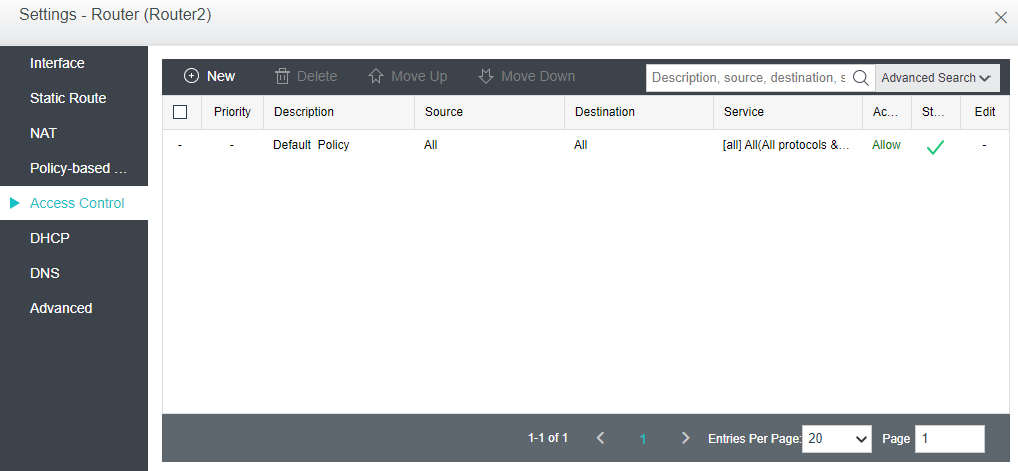
To add an access control policy, click Add to enter the following page 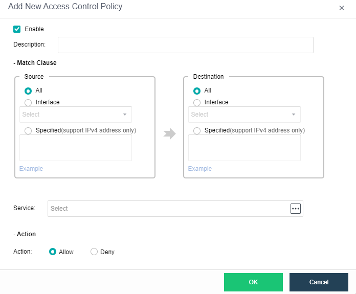
Enabled: Select this option to enable the policy.
Description: Descriptive information of the policy.
Filter: Specifies Source and Destination.
All: Indicates any source or destination IP address.
Interface: Specifies source or destination interface.
Specified: Specifies specific source or destination IP address.
Service: Specifies service, such as WEB, DNS and other services.
Action: Specifies action against matching packets. To allow the packets, select Allow. To reject packets, select Reject.
DHCP is used to automatically assign IP addresses to virtual machines. You can configure DHCP address pool on the IP Address Pool tab and view status of assigned IP addresses on the Status tab. 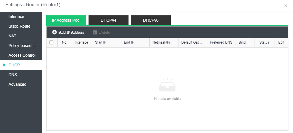
To add IP address pool, click Add IP Address on the IP Address Pool tab.
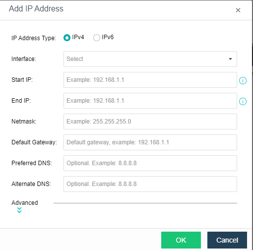
On the above page, specify IP Address Type, Interface, Start IP, End IP, Netmask, Default Gateway, Preferred DNS and Alternate DNS.
Advanced: You can specify Preferred WINS, Alternate WINS, and Lease. As for Lease, it specifies the period that allocated IP addresses can be used, as shown below: 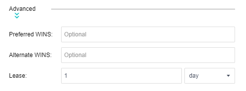
On the DHCPv4/DHCPv6 tab, it displays the following information: Interface, IP Address, Host Name, MAC, Time Assigned, Lease Expiration and Bindings. To bind IP address with a corresponding host, click Bind and specify MAC address. Thus, the IP address will be only assigned to the host with the specified MAC address. 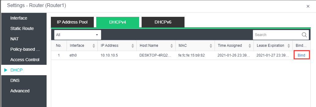
DNS proxy can help to resolve domain names for the devices connected to the virtual router. To edit DNS server, click Edit. 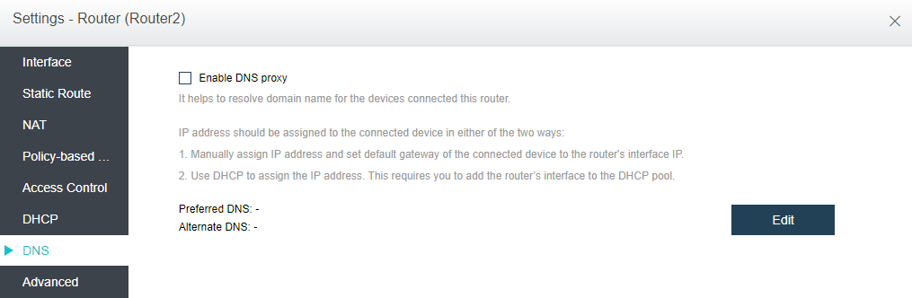
On the Advanced tab, you can enable high availability (HA) and specify a node to run the virtual router. 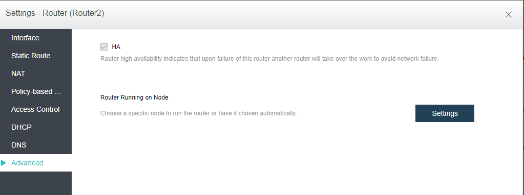
To enable HA, select the option HA. If HA is enabled, a second router will be built on another node and synchronize data in real time. If one node fails, the second router will take over seamlessly. However, synchronizing data between the two routers will consume extra network bandwidth.
Without high availability enabled, the router will still recover to a second node, but it will take longer to get up and running
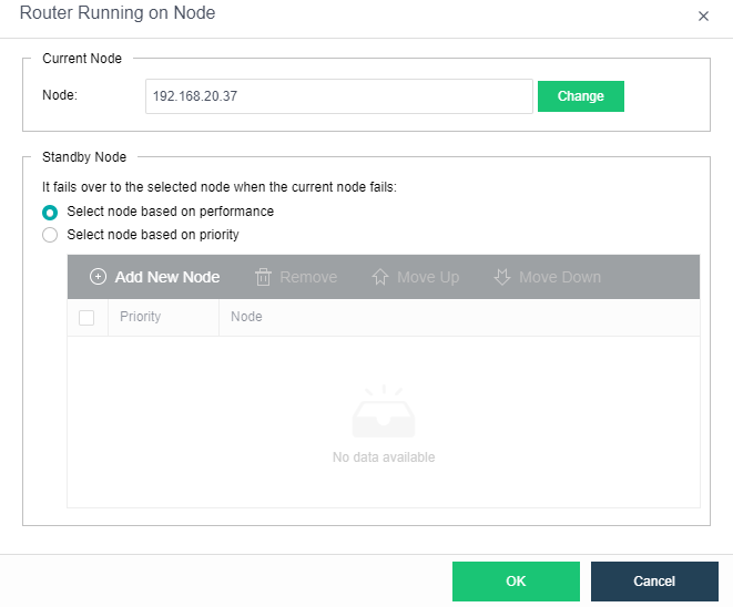
Router Running on Node: By default, the node where the router runs is automatically selected according to the settings on the following page. You can change the current node running the router as per your need.

 {{ $t('index.defaultHeader.chromeBrowserTip') }}