{{ secondMenu.name }}


Function Description:
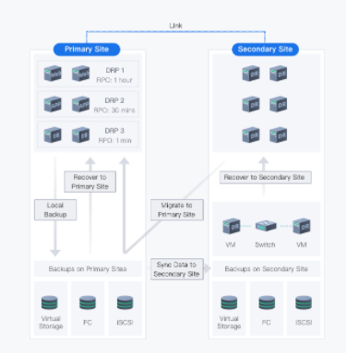
The Sangfor disaster recovery solution adopts the Scheduled backup/aDR solution, and both the primary and standby sites are Sangfor enterprise cloud platforms.
Provide common backup or CDP backup solutions locally, and back up the virtual machine to the primary site backup repository. When the virtual machine fails, the entire virtual machine can quickly recover from the local protection data. The best can achieve RPO=1s and RTO=2 minutes (when the customer's RPO requirement is at the second or minute level, the CDP backup solution is recommended. When the customer's RPO requirement is at the hour level or more, the ordinary backup solution is recommended).
Provide virtual machine-level disaster recovery functions with different RPOs (minimum 1s) in different places. Based on local backup, the data of the primary site is asynchronously replicated to the secondary site. As a result, when the primary site fails, the virtual machine can be quickly pulled up at the secondary site. The minimum RTO is 10 minutes, significantly shortening the business interruption time.
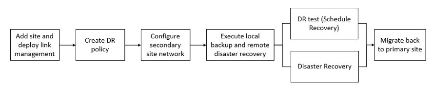
The main configuration process of disaster recovery is shown in the following figure.
4.8.4.1.1Add A Disaster Recovery Site
Function Description:
SCP supports multi-site DR and supports synchronization between the primary site and the secondary site. In this case, business can be quickly recovered from the secondary site when the primary site fails.
Precautions
Ensure that the time of the HCI primary and secondary sites are in synchronization with that of SCP. We recommend that you deploy an NTP server.
Prerequisite
The primary and secondary DR sites have been added to the resource pool.
Steps:
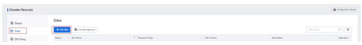
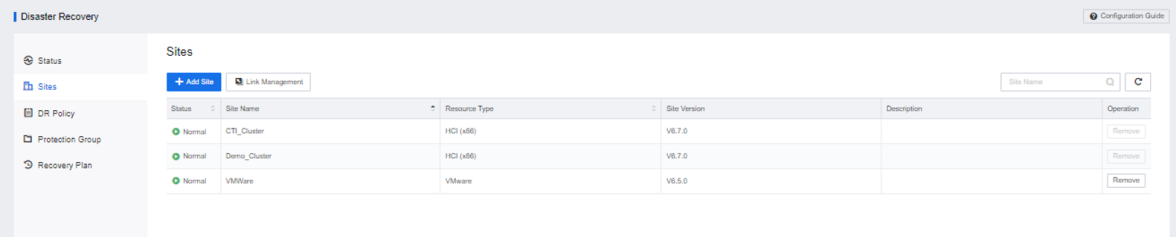
Step 1.Go to Reliability > Disaster Recovery > Sites to add the resource pool as a disaster recovery site.
Step 4.The disaster recovery site is added successfully.
4.8.4.1.2Add A Disaster Recovery Link
Function Description:
This section specifies the connection relationship of all sites through disaster recovery links and supports modification of transmission rates, disaster recovery interface, transmission encryption, and link alarms.
Precautions:
Prerequisite
The DR primary and secondary sites have been added to the resource pool, and the DR site has been added successfully.
Steps:
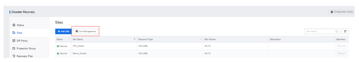
Step 1.Go to Reliability > Disaster Recovery > Sites interface. Click Link Management to configure a DR link for the DR site.
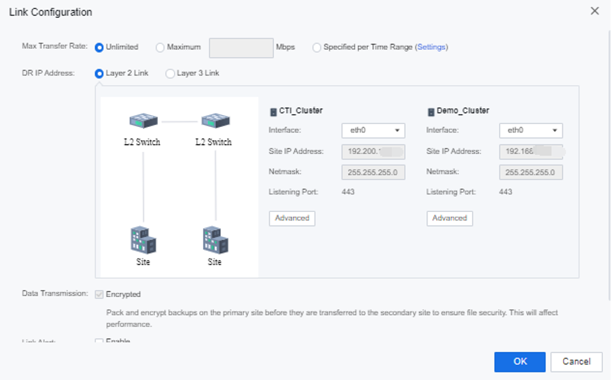
Step 2.Configure the link:
Step 3.Click Advanced to configure the interface for the disaster recovery link. Inter-Site Communication Interfaces refer to the interface that transmits disaster recovery data when the node acts as the cluster controller.
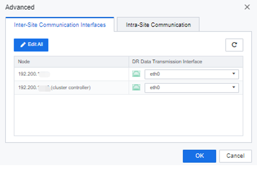
Step 4.Intra-Site Communication Interfaces refer to the interfaces through which the non-active node in the cluster transmits disaster recovery data to the cluster controller.
4.8.4.1.3Configure The Disaster Recovery Policy
Function Description:
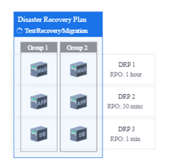
It supports setting disaster recovery strategies for virtual machines and configuring parameters such as backup schedule and transmission frequency. It also supports setting disaster recovery strategies for virtual machines with different RPO requirements, such as WEB systems, application systems, and database systems, to meet the needs of data-tiered protection.
Precautions:
| Windows 7 32-bit/64-bit |
Windows 8 32-bit/64-bit |
Windows 10 |
| Windows 11 |
Windows Server 2003 32-bit/64-bit |
Windows Server 2008 32-bit/64-bit |
| Windows Server 2008 R2 |
Windows Server 2012 |
Windows Server 2016 |
| Windows Server 2019 |
Windows Server 2022 |
|
a. The COM+ System Application service has been started, with the startup type set to Manual.
b. The COM+ Event System service has been started, with the startup type set to Automatic.
c. The Volume Shadow Copy service is not running, with the startup type set to Manual.
Prerequisite
Steps:
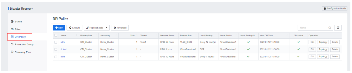
Step 1.Enter the Reliability > Disaster Recovery > DR Policy and click the New button.
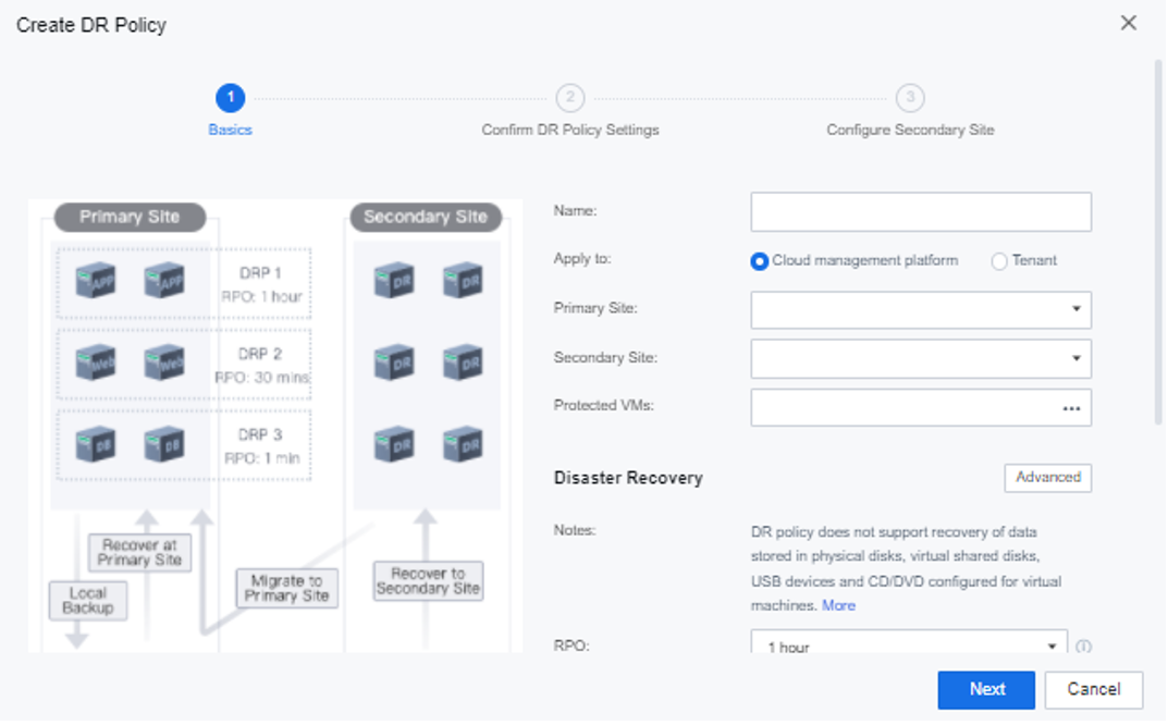
Step 2.Configure the disaster recovery policy:
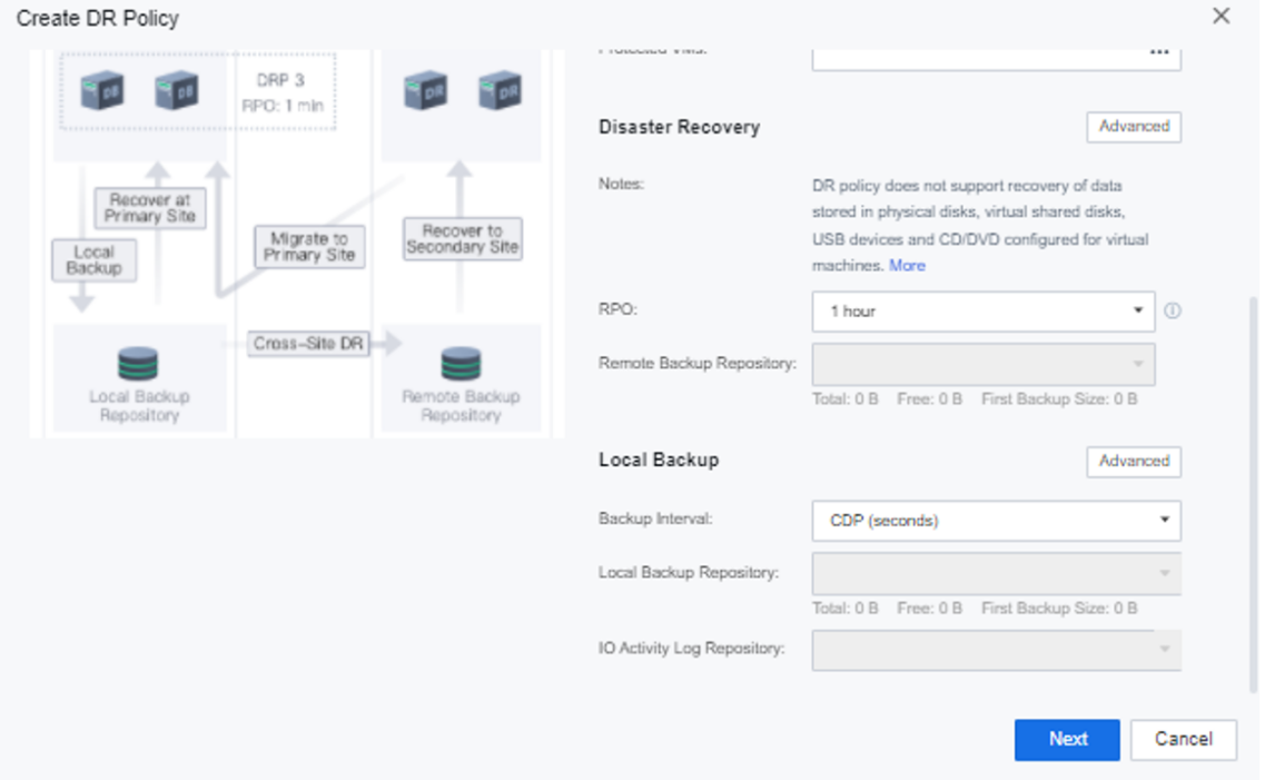
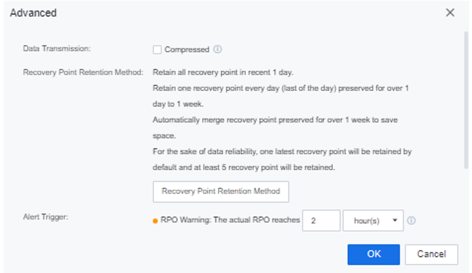
Step 3.Click Advanced of the Disaster Recovery to configure whether to compress the transmission, the recovery point retention mode and the alarm threshold for the disaster recovery policy.
Step 4.Create different disaster recovery policies for the different VM groups according to the required RPO. After the disaster recovery policy is configured, you can select the disaster recovery policy and click Execute to complete the first data backup and disaster recovery transmission. Or use the Replica Seed function to export the full data of the virtual machine at the primary site and import it to the secondary site through the manual transmission to complete the first data backup and disaster recovery transmission. After completing the configuration, click the green button to enable or disable the disaster recovery policy.
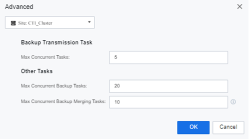
Step 5.On the Advanced Settings page, it is possible to configure DR limits for different resource pools. The number of concurrent backup transmission tasks is the number of concurrent data transfers from the primary site to the standby site.
Number of concurrent tasks: The number of concurrent backups and merge tasks is the number of concurrent tasks that can be performed at the same time when multiple VM trigger a backup and merge task.
4.8.4.1.4Replica Seed
Function Description:
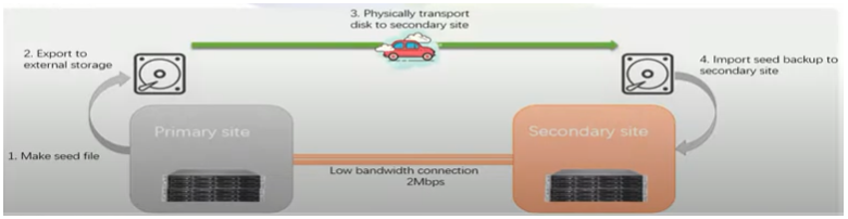
After creating a disaster recovery policy, you can export and save the full backup of the virtual machine to a disk (such as a mobile hard disk, mechanical disk, low-capacity NAS, etc.) through a seed file and transport it to the disaster recovery site to complete the initial replication of the virtual machine. For subsequent data sync, transferring the full backup is unnecessary. Only the incremental data based on the seed backup can be transferred.
Precautions:
Prerequisite
Steps:
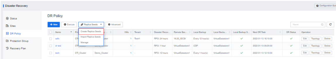
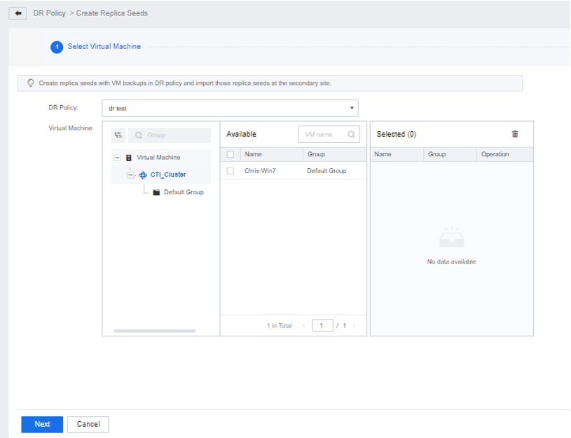
Step 1.Connect the medium used to transmit seed files to the HCI platform of the primary site, navigate to Disaster Recovery > DR Policy, and click Replica Seeds > Create Replica Seeds.
Step 2.Select a disaster recovery policy and click Next.
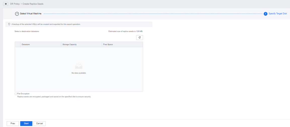
Step 3.Select the export destination datastore as the transmission medium of the replica seed file and check the File Encryption checkbox to encrypt and pack the replica seed file and save it to the specified hard disk to ensure the security of the file. Exporting the replica seed file will perform a backup on the virtual machine and then export it and will not affect the original backup chain.
Step 4.Click Start to enter the export process.
4.8.4.1.5Add Protection Group
Function Description:
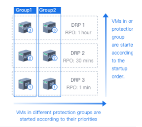
The virtual machine in multiple disaster recovery policies is supported to form a protected group. Add WEB1, APP1, and DB1 to the protected group 1. You can perform drills on different RPO virtual machines in protected group 1. Migrate and restore actions. It supports manually configuring the priority order according to the dependencies of the virtual machine in the protection group to ensure that the business can be started. At the same time, it supports configuring the priority for multiple protection groups and guarantees the vital business first during the recovery.
Precautions:
None.
Prerequisite
The disaster recovery policy has been successfully created, and the disaster recovery virtual machine has been added.
Steps:
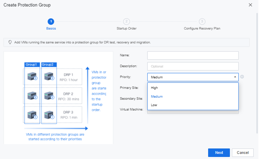
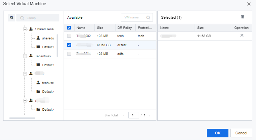
Step 1.Enter the Reliability > Disaster Recovery > Protected Group interface and click the New button to create a protection group. Select the importance level for the group. The group with a higher priority can perform tasks such as backup, data transfer, recovery, drill, and relocation.
Step 2.Configure the virtual machine and add the virtual machine of the same business group to the disaster recovery business group 1.
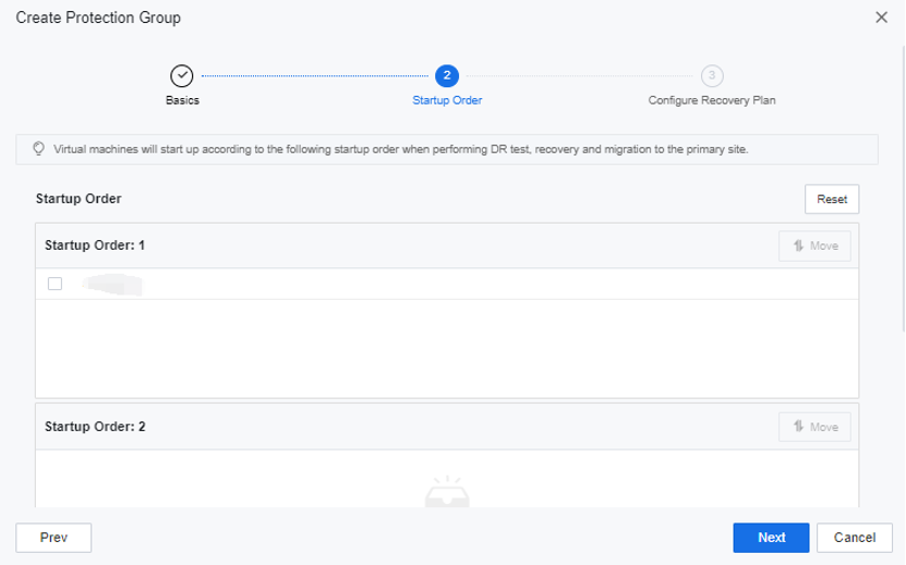
Step 3.Configure the boot sequence in the group and select a safe boot sequence according to the business architecture logic. For example, start the database virtual machine first and the OA and APP application virtual machine after the waiting time.
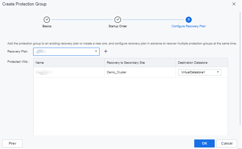
Step 4.You can choose to add a group to an existing or newly created recovery plan, allowing multiple protection groups to perform disaster recovery drills, data transmission, and disaster recovery relocation operations at the same time.
Step 5.The protection group configuration is complete.
4.8.4.1.6Recovery Plan
Function Description:
Create a recovery plan for the disaster recovery virtual machine. When multiple services need to be drilled, multiple protection groups can be added to the same recovery plan, and the recovery plan can be drilled, restored, and relocated. The group will prioritize the recovery and retrieving actions for businesses with high priority.
Precautions:
Prerequisite
The disaster recovery virtual machine has been successfully added to the protection group.
Steps:
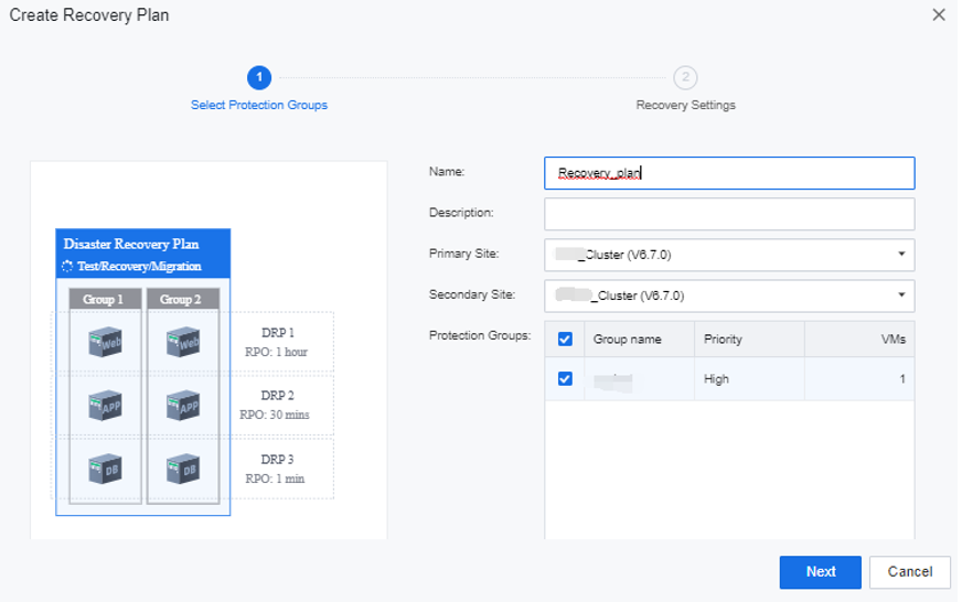
Step 1.Enter the Reliability > Disaster Recovery > Recovery Plan, and click the New button to create a protection group. Select the importance level for the business group. The business group with a higher priority can perform tasks such as backup, data transfer, recovery, drill, and relocation.
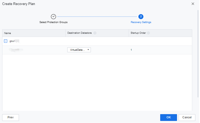
Step 2.In Recovery Settings, you can see the destination storage location and the startup order during restoration.
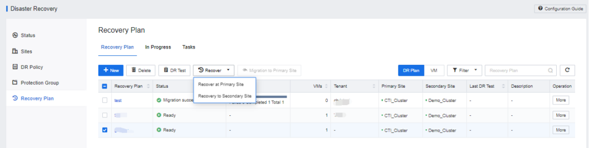
Step 3.Select a recovery plan and perform operations such as DR Test, Recover, and migrate to the primary site at the top of the page.
4.8.4.1.7DR Test
Function Description:
Supports disaster recovery drills for the virtual machines in the protection group. During the disaster recovery drill, a new drill virtual machine will be generated at the secondary site, which has no impact on the virtual machine at the primary site and the disaster recovery standby machine.
Precautions:
In order not to affect services, the drill virtual machine-generated by the disaster recovery drill is not connected to the virtual network. To perform post-drill service verification, you need to separately plan the drill network and manually connect the drill virtual machine to the drill network.
Prerequisite
The protection group has been successfully added to the recovery plan.
Steps:
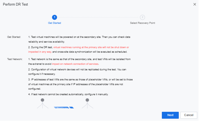
Step 1.Go to the Reliability > Disaster Recovery > Recovery Plan interface, select the recovery plan that needs to be drilled, and click the DR Test button above to view the description of the drill function and choose whether to use the reserved node resources to perform the drill on the virtual machine.
Step 2.Click Next to select the recovery point of the virtual machine. Next, you can choose whether to synchronize the data of the primary site for the drill. If you choose Start DR test without syncing data, the drill virtual machine will be directly launched at the secondary site, and the drill virtual machine can choose the recovery point saved on the secondary site. If you choose to Sync data before testing, the current virtual machine state of the primary site will be synchronized. After arriving at the secondary site, start the virtual machine with the current status of the virtual machine at the primary site.
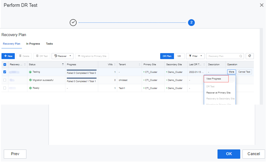
Step 3.Click OK to start the test. During the test, you can click More > View Task Progress to see the progress of the test.
Step 4.After the DR test is completed, a corresponding DR test virtual machine (non-disaster recovery backup machine) will be added to the standby site. The drill virtual machine is not connected to the physical edge.
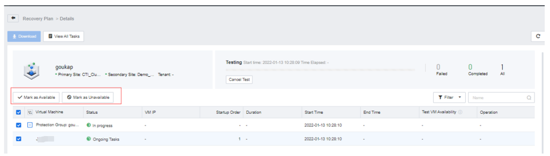
Step 5.Enter the View Progress interface, verify the virtual machine's services and mark it as available. The virtual machine not marked as Available or Unavailable will be recorded in the DR test report.
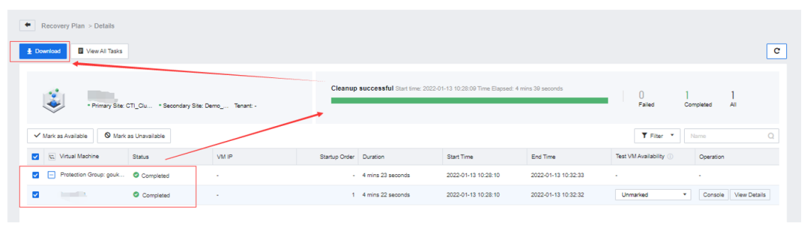
Step 6.After the DR test is complete, click Finish Test and Clean Up to delete the DR test virtual machine and data, including all the available and unavailable DR test virtual machines, and delete the network devices and VM groups generated during the DR test.

Step 7.After the DR test is cleaned up successfully, select the disaster recovery business group and click Download to obtain the detailed DR Test report.
4.8.4.1.8Recover At Primary Site
Function Description:
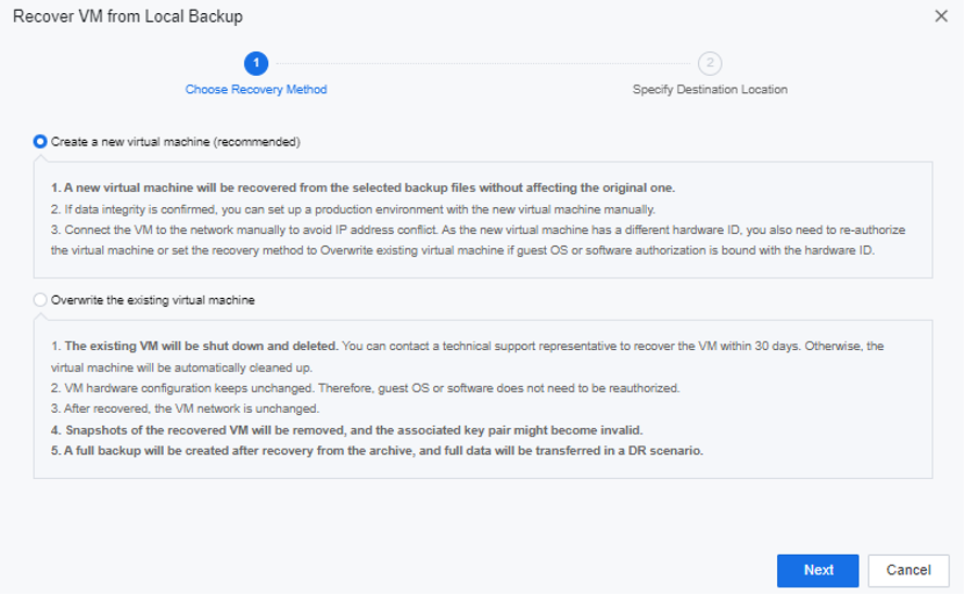
When data loss occurs on the virtual machine at the primary site, you can select Recover at Primary Site to restore the disaster-tolerant virtual machine from the primary site through backup. There are two ways to restore to a new virtual machine and to overwrite the original virtual machine. Create a new virtual machine will create a new virtual machine from the backup point, and the original virtual machine will not be affected. Overwrite the existing virtual machine will shut down and delete the original virtual machine.
Precautions:
Prerequisite
The protection group has been successfully added to the recovery plan.
Steps:
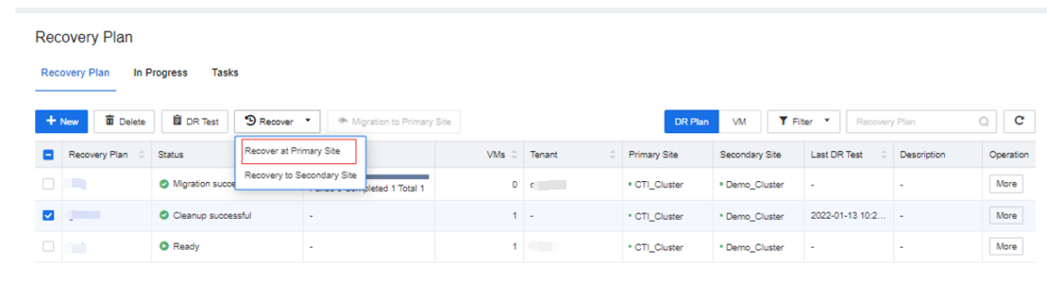
Step 1.Navigate to the Reliability > Disaster Recovery > Recovery Plan, select the recovery plan that needs to be drilled, and click on the Recover at Primary Site button.
Step 2.Select the recovery method. It is recommended to choose to generate a new virtual machine. This method's virtual machine must be manually connected to the production network. Overwrite the existing virtual machine will close and delete the original virtual machine.
Step 3.Select the backup point and destination location of the recovered virtual machine.
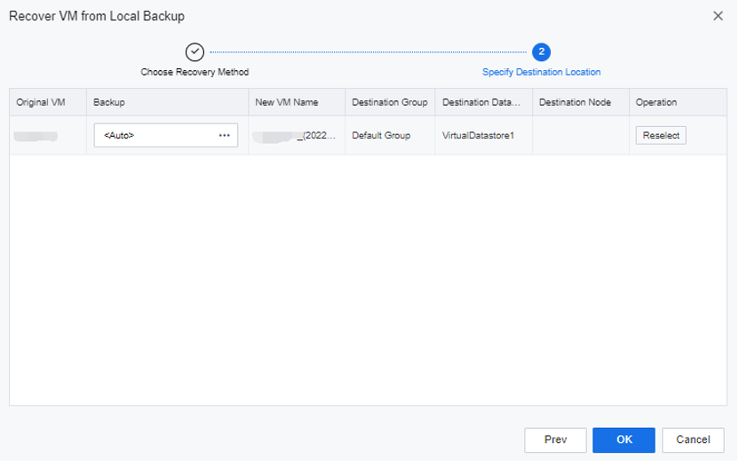
Step 4.Click OK to start restoring the virtual machine.
4.8.4.1.9Recover To Secondary Site
Function Description:
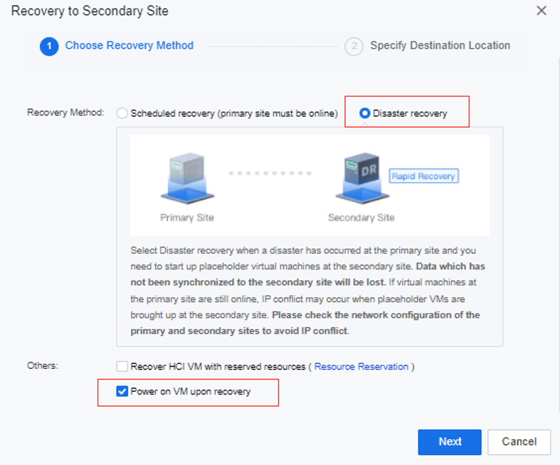
When a disaster occurs at the primary site, select Disaster Recovery to pull up the disaster recovery standby machine from the secondary site. The data not synchronized to the secondary site will be lost.
Precautions:
During post-disaster recovery, if the virtual machine at the primary site is still online, the DR at the secondary site may cause IP conflicts.
Prerequisite
The protection group has been successfully added to the recovery plan.
Steps:
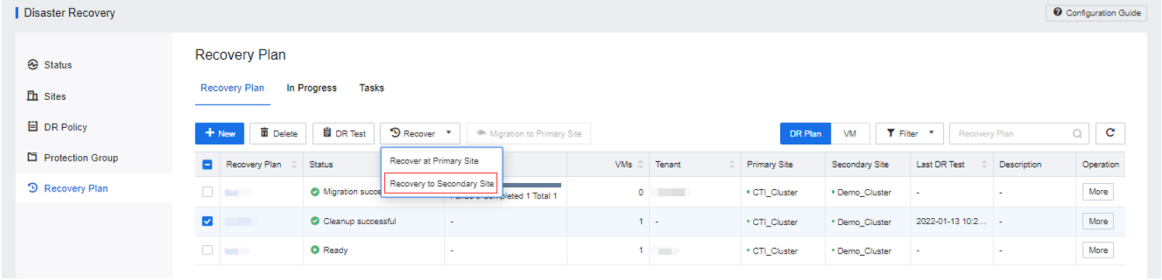
Step 1.Go to the Reliability > Disaster Recovery > Recovery Plan interface, select the recovery plan that needs to be drilled, and click the Recover to Secondary Site button.
Step 2.Select Disaster recovery as the recovery method and select Power on VM upon recovery for others. You can also configure resource reservations and select Recover HCI VM with reserved resources.
Step 3.Click the corresponding recovery plan More > View progress button. You can see the detailed information about the recovery.
Step 4.After the secondary site is successfully restored, select the disaster recovery protection group, and click Download to obtain the detailed disaster recovery report. It supports the configuration of subscription to the report and sends the report to the specified mailbox via email.
4.8.4.1.10Migration To Primary Site
Function Description:
When the primary site is recovered from a disaster, the virtual machine data of the secondary site is relocated to the primary site.
Precautions:
During the migration, you need to manually shut down the virtual machine at the secondary site according to the task prompts.
Prerequisite
The primary site recovered from the disaster.
Steps:
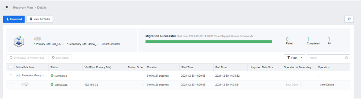
Step 1.Navigate to Reliability > Disaster Recovery > Recovery Plan, select the recovery plan that needs to be drilled, and click the Migration to Primary Site button.
Step 2.Support to modify the data synchronization interval, trigger synchronization threshold, and wait for manual shutdown timeout during the migration phase.
Step 3.Select the datastore for the virtual machine to be relocated and click OK.
Step 4.The interface will display the Waiting for shutdown prompt during migration to the primary site. You need to manually shut down the disaster recovery virtual machine at this time, and the migration task can continue.

 {{ $t('index.defaultHeader.chromeBrowserTip') }}