{{ secondMenu.name }}


Function Description:
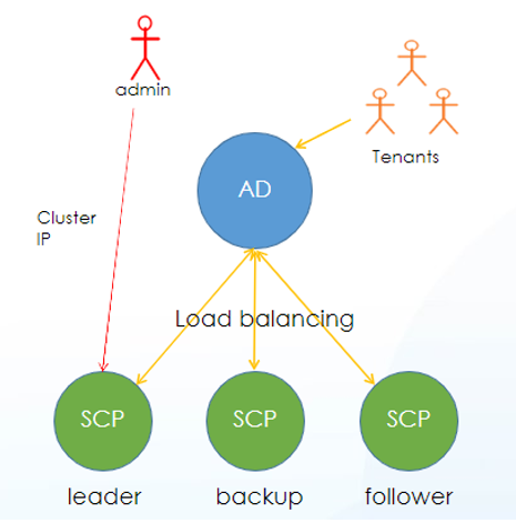
Sangfor SCP supports cluster mode deployment, switching SCP from stand-alone mode to cluster mode, providing horizontal expansion and high availability capabilities. After switching to the cluster mode, tenants are supported to access each node of the SCP cluster through the load function of AD, and the admin logs in to the controller node through the cluster IP to manage the SCP cluster.
Precautions:
Recommended configuration
The SCP cluster deployed with three nodes significantly improves the transaction processing capabilities of the cloud computing platform and provides high concurrency and high availability features for large-scale delivery scenarios. In cluster mode, it is recommended to use three nodes for deployment. The configuration specifications are as follows:
| SCP Configuration |
Number of Tenants |
Number of Tenant Users |
Concurrency Number of HCI Cluster |
Number of Managed Cluster |
Number of Physical Node |
Number of Virtual Machine |
| 32 Core 64G *3 |
2000 |
4000 |
4000 |
128 |
1024 |
60000 |
Function Description:
For the SCP single network card scenario, the situation where the management network and the business network are integrated, small-scale delivery scenarios are recommended.
Precautions:
Load balancing cannot be done in a single network card scenario.
Prerequisites:
Ports 4480 and 443 can be accessed.
Steps:
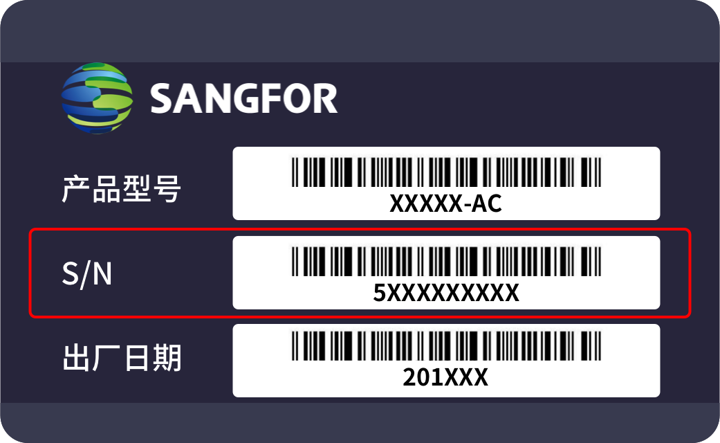
Step 1.Log in to the HCI platform console, select the SCP virtual machine, click Edit, add USB hardware, and map the license key to the virtual machine. (Only the SCP active node needs to be added, the other two nodes can skip). Edit the network card, so it is reachable between the second-and third-layer network. After this, click OK.
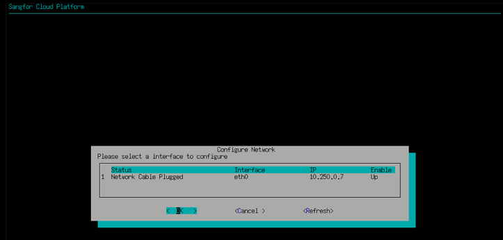
Step 2.SCP single network card configuration: log in to the SCP console, click on any part of the virtual machine console, type enter on the keyboard, enter the maintenance mode, and enter the password (the initial password is admin). Use the keyboard ↑↓ key to select Setup Network, press enter key on the keyboard, configure the IP address, netmask, and gateway, and click the OK button.
Step 3.Follow the above steps to complete the deployment and network card configuration of the other two SCP nodes in sequence.
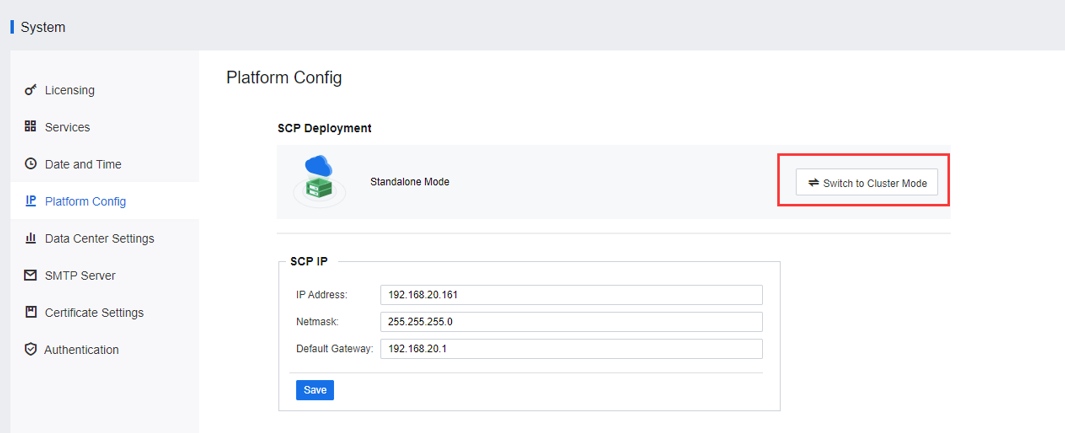
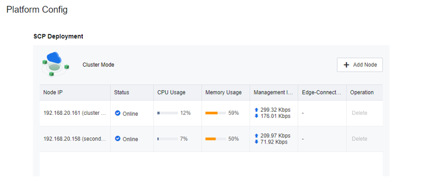
Step 4.Log in to the main SCP console, navigate to System > Platform Config, and click the Switch to Cluster Mode button to switch the SCP platform deployment mode to cluster mode.
![]()
After the SCP is switched to the cluster mode, it cannot be switched back to the stand-alone mode.
Step 5.Enter the Cluster IP and Netmask in the pop-up dialog box. You must ensure it is in the same network segment as the platform IP.
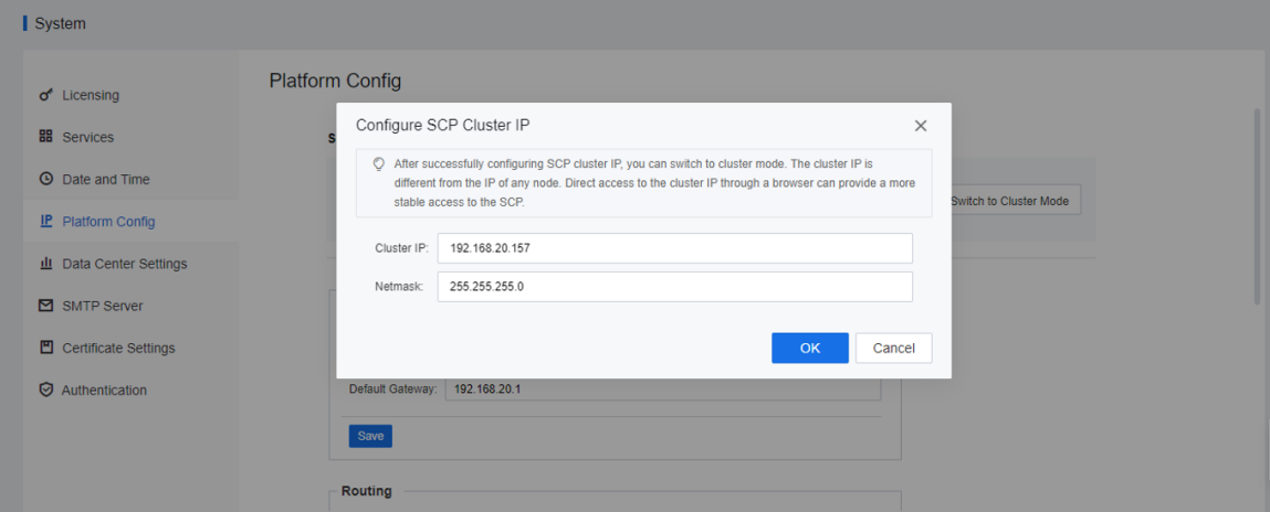
Step 6.Click OK to switch to cluster mode, and the current node is switched to the cluster controller node of the cluster.
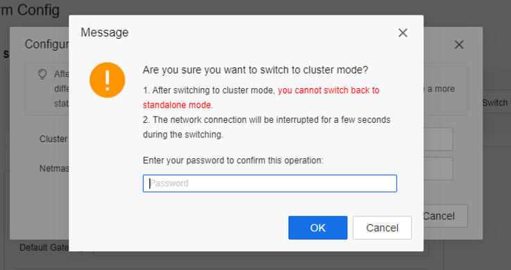
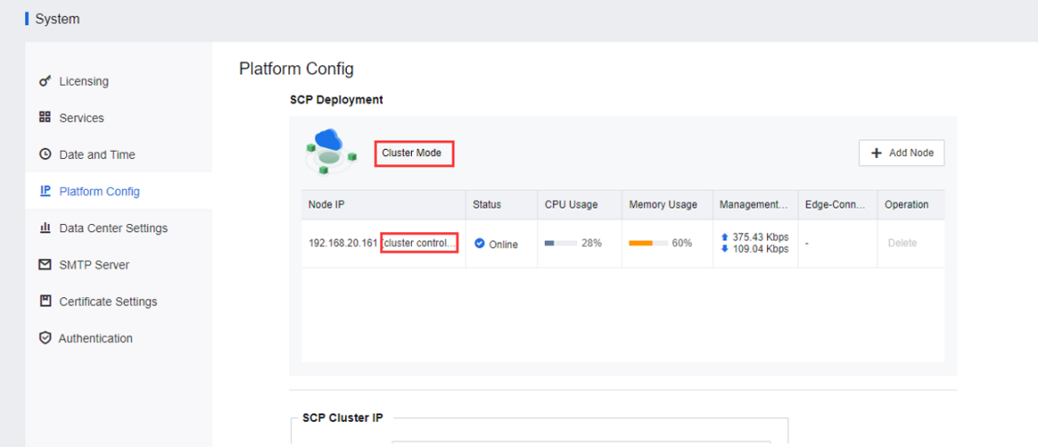
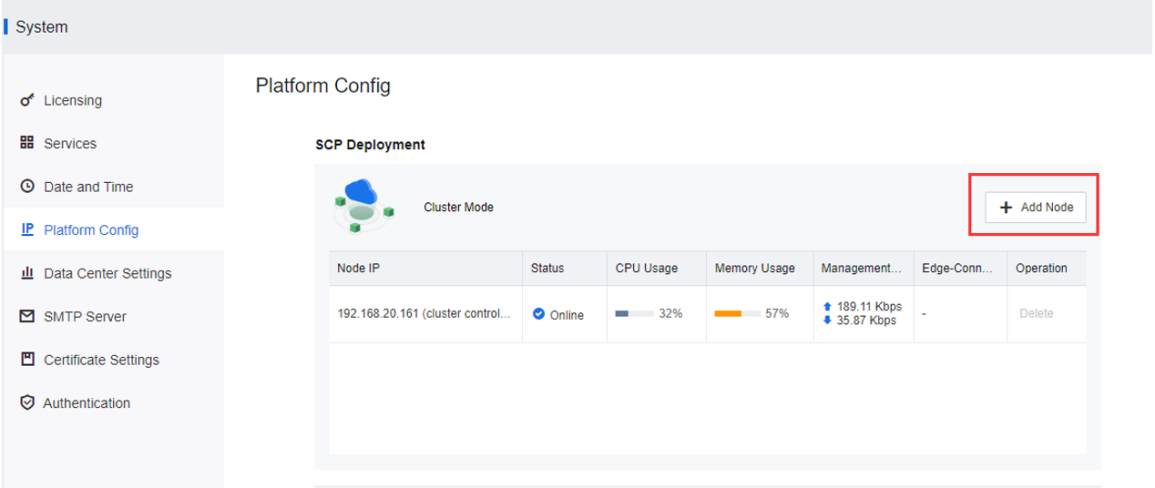
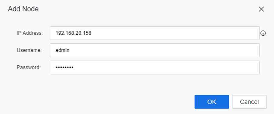
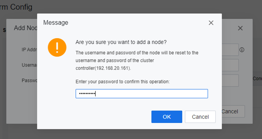
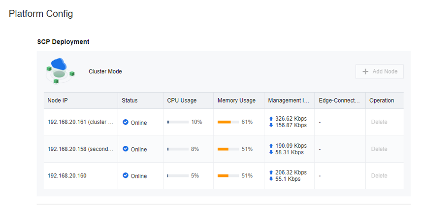
Step 7.Continue to add the standby node, click Add Node, enter the standby node IP address, username, and password, click OK, enter the current admin password, and complete the addition of the standby node.
Step 8.Continue to add cluster nodes until SCP Cluster is successfully formed.
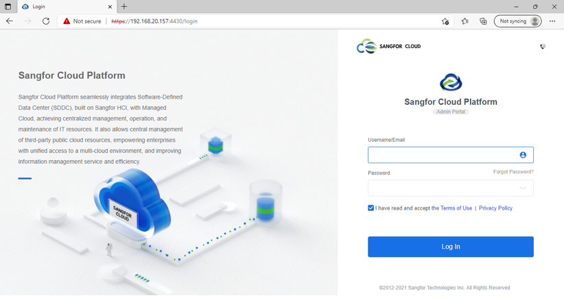
Step 9.After the deployment is complete, open the browser, the administrator logs in at https://{cluster IP}:4430, and the tenant logs in at https://{cluster IP}:443.
Function Description:
For the SCP multiple network card scenario, which separates the management network and the business network, it is recommended to use it in a large-scale delivery scenario.
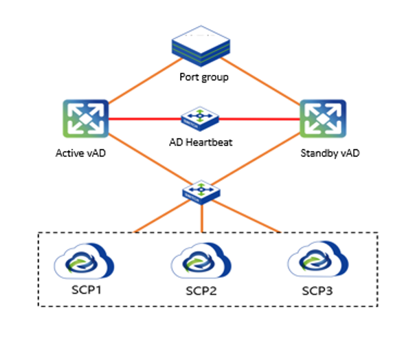
Topology Overview
Precautions:
The SCP multiple network card scenario needs to be configured with load balancing. There is no mandatory requirement for the vAD version. It is recommended to use vAD7.0.8R4, and the AD High Availability deployment is recommended.
Prerequisites:
Ports 4480 and 443 can be accessed.
Steps:
Step 1.Log in to the HCI platform console, select the SCP virtual machine, click Edit, add USB hardware, and map the license key to the virtual machine. (Only the SCP active node needs to be added, the other two nodes can skip). Edit the network card, so it is reachable between the second-and third-layer network. After this, click OK.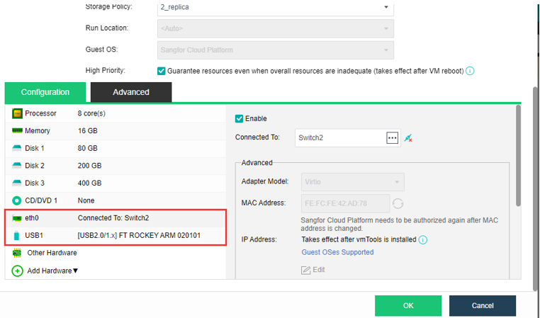
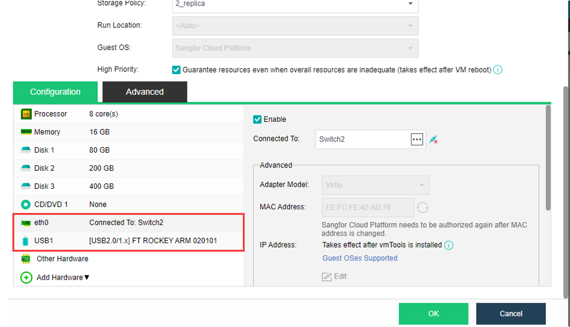
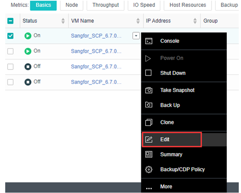
Step 2.Enter the HCI virtual machine list, find the SCP virtual machine, right-click the Edit button, and enter the Edit virtual machine page.
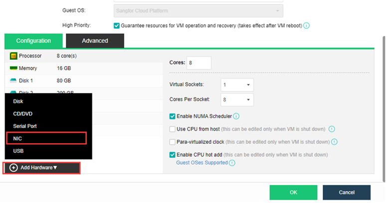
Step 2.Click Add Hardware to add second network cards for SCP. Then, edit the network card to connect to the tenant's business network.
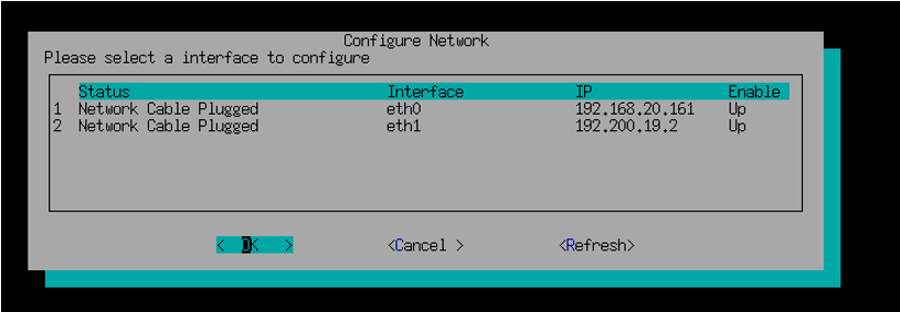
Step 3.Log in to the SCP console, click on any part of the virtual machine console, type Enter on the keyboard, enter the maintenance mode, and enter the password (the initial password is admin). Use the keyboard ↑↓ key to select Configure Network and type the enter key on the keyboard to configure the IP address, netmask, and gateway for the SCP multiple network card, and click the OK button.
![]()
Step 4.Follow the above steps to complete the dual network card configuration for the other two SCP nodes.
Step 5.Log in to the main SCP console and switch to cluster mode. For switching the cluster mode and adding nodes in the cluster, please refer to chapter 2.3.2.1 SCP Single NIC Scenario, steps 4-7.
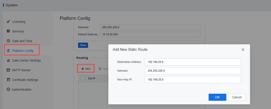
Step 6.Navigate to System > Platform Config > Routing, and click the New button. The Destination Address is the gateway of the local PC, and the Next-hop IP is the gateway of the cluster management network.
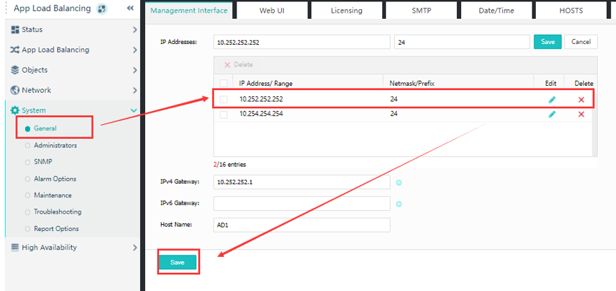
Step 1.Configure the management interface IP address. Log in to the console of the main AD1, navigate to System > General > Management Interface, and configure the management IP of the main AD1.
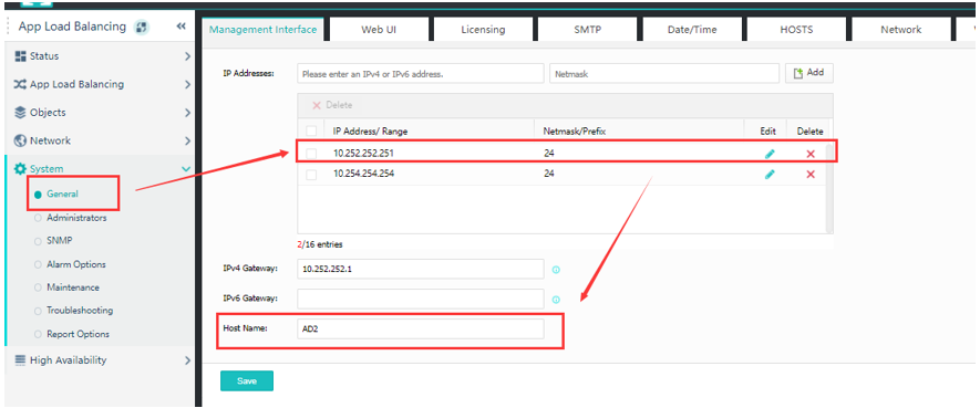
Step 2.After this, log in to the standby AD2 console to complete the configuration of the management IP.
Step 3.Configure high availability for both vAD. Navigate to High Availability > Device Basics of the main AD1, select Enable for Active-standby mode, and Active Device for Status.
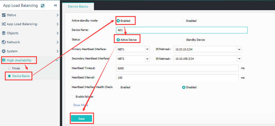
Step 4.Perform the same steps above for AD2.
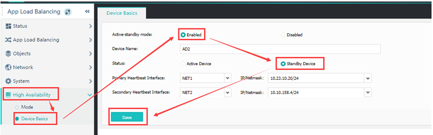
Step 5.After completing the high-availability configuration, enter the High Availability > Device Basics page of the active and standby ADs to check whether the active or standby status is normal.
Step 6.Navigate to the Network > Network Interface page and configure the
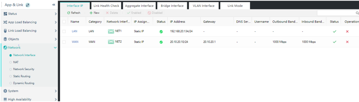
![]()
Here you only need to configure on the active device, and the backup will automatically synchronize the configuration in the standby device.
The configuration parameter description is shown in the following table.
| Network Interface |
Description |
| Network Interface - LAN |
Connect the production port of the SCP node to communicate with the SCP node. |
| There is no need to configure the gateway, DNS, name, inbound bandwidth, and outbound bandwidth. |
|
| Status: Enabled. |
|
| Network Interface - WAN |
By connecting to the external network, the tenant can access the AD through this IP address and then access the SCP through the SCP production port. |
| Outbound Bandwidth and Inbound Bandwidth: 1000Mbps is recommended. |
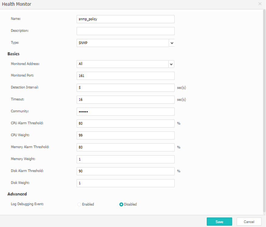
Step 7.Navigate to the App Load Balancing > Node Pool > Health Monitor page, configure the business health check policy, and configure the SNMP policy.
The configuration description is shown in the following table.
| Attributes |
Description |
| Name |
Configure Policy Name |
| Type |
Choose SNMP |
| Password Enquiry |
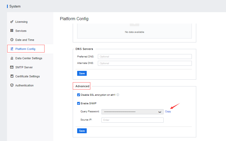
Enter the SNMP query password. You can get the query password by logging into the SCP platform. Then, navigate to System > Platform Config > Advanced, and click the Copy button beside Query Password.
|
| CPU weight |
Set as 99. |
| Memory Weight |
Set as 1. |
| Memory alarm threshold |
Set as 80. |
| Disk weight |
Set as 1. |
| Other configurations |
Use the default settings. |
Table 1:SNMP Configuration Specification
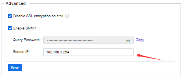
Back to the SCP platform, navigate to System > Platform Config > Advanced to configure the Source IP. Fill in the business IP address used to interconnect with SCP on vAD.
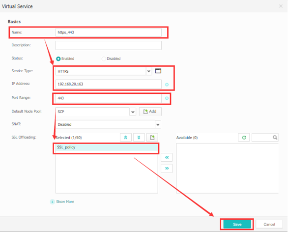
Step 8.Configure the Node Pool. Create two address pools. The ports are 443 and 4480, respectively, the addresses must be the service addresses of the SCP, and the SNMP policy in the previous step is used for detection. Navigate to the App Load Balancing > Node Pool page:
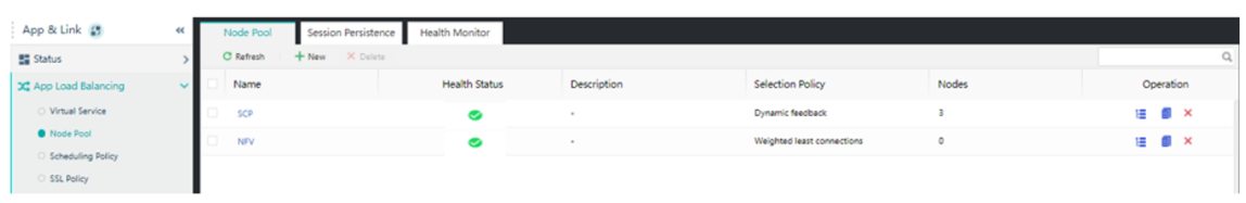
• Web node pool configuration
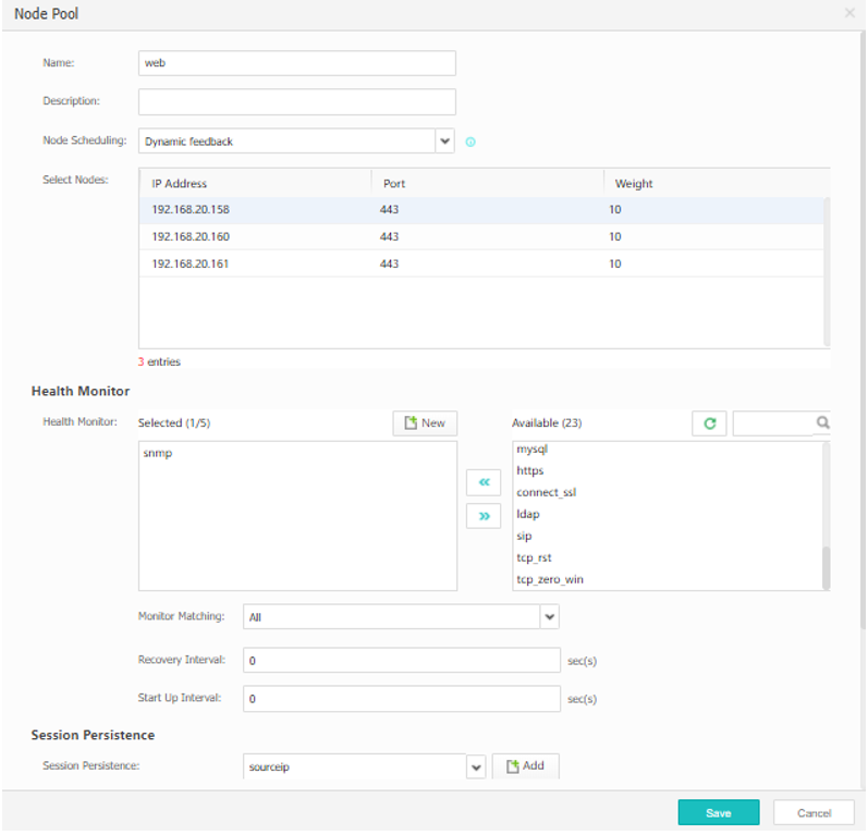
The configuration description is shown in the following table.
| Attributes |
Description |
| Node Scheduling |
Select “Dynamic Feedback” |
| Select Node |
Add the service IP of the SCP node. The port number is 443, the weight is 10, and the priority is 1. |
| Health Monitor |
Select custom SNMP Policy created previously. |
| Others |
For Heavy Load, select Set to Scheduling. For Connections, select All in any status. |
| Session Persistence |
Select sourceip |
| Other configurations |
Use the default settings. |
Table 2:Node Pool Configuration Specification
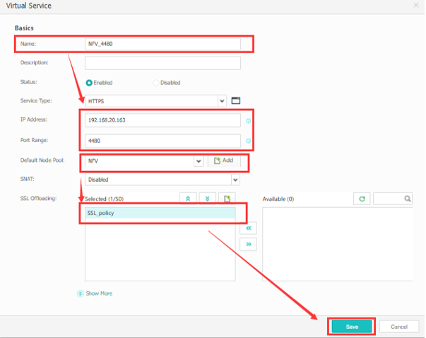
• NFV node pool configuration
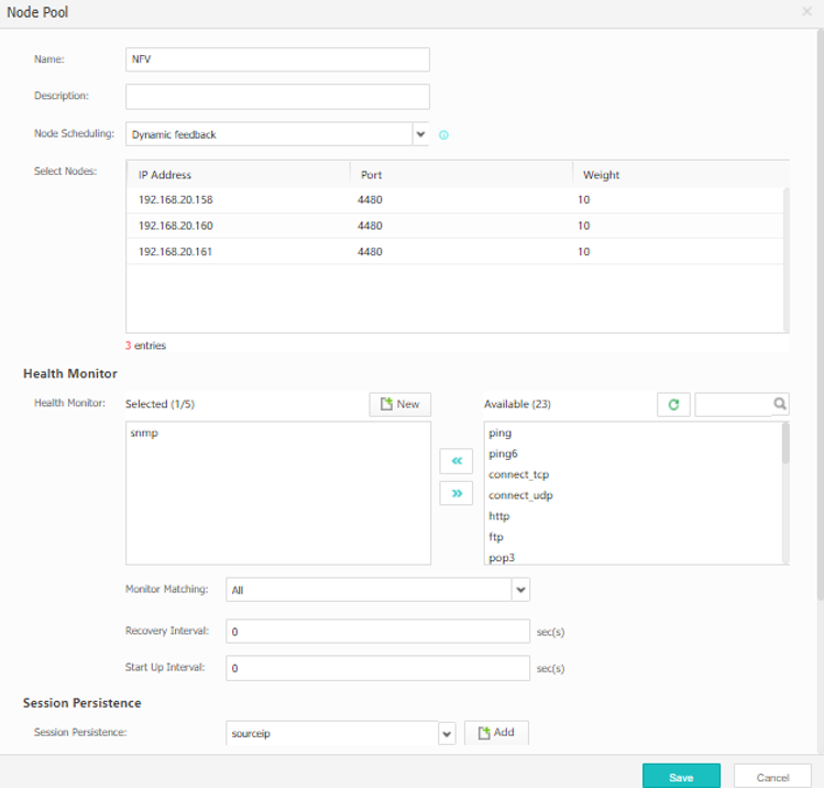
The configuration description is shown in the following table.
| Attributes |
Description |
| Node Scheduling |
Select “Dynamic Feedback” |
| Select Node |
Add the service IP of the SCP node. The port number is 443, the weight is 10, and the priority is 1. |
| Health Monitor |
Select custom SNMP Policy created previously. |
| Others |
For Heavy Load, select Set to Scheduling. For Connections, select All in any status. |
| Session Persistence |
Select sourceip |
| Other configurations |
Use the default settings. |
Table 3:NFV Node Pool Configuration Specification
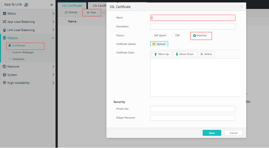
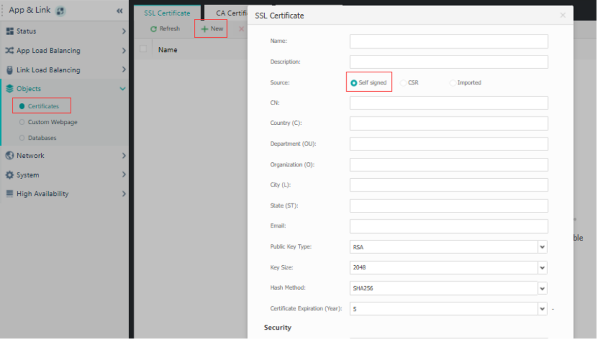
Step 9.Configure certificate offload and apply payload.
Add Certificate: There are two ways to add a certificate here. You can choose to import a certificate or manually add a certificate.
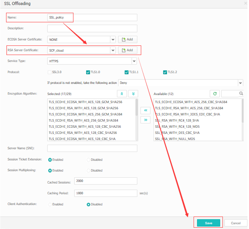
Next, navigate to App Load Balancing > SSL Policy > SSL Offloading and click New to create an SSL offload policy.
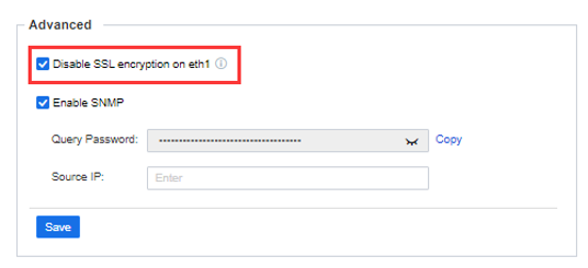
Step 10.Turn off HTTP offloading for WAF
Log in to the SCP console, go to the System > Platform Config > Advanced page, and check the Disable SSL encryption on eth1 checkbox.
Step 11.After the deployment is complete, open a browser, the administrator logs in via https://{eth0IP}, and the tenant logs in via https://{eth1IP}.

 {{ $t('index.defaultHeader.chromeBrowserTip') }}