


{{ secondMenu.name }}





The active-standby deployment is also called dual-device hot standby deployment. In this mode, one device is in working status and the other is in the hot standby status. The two devices detect whether configuration synchronization and session exist in peer devices using heartbeat interfaces. When there are problem switchover triggers in the active device, it will automatically switch the service to the standby device and keep the service continue through session synchronization and other mechanisms, thus ensuring the stable operation of the service. This function supports active-standby deployment in route mode and active-standby deployment in network bridge mode. The network bridge mode includes a transparent mode and a virtual network cable mode.
Configuration Example of Active-Standby Deployment
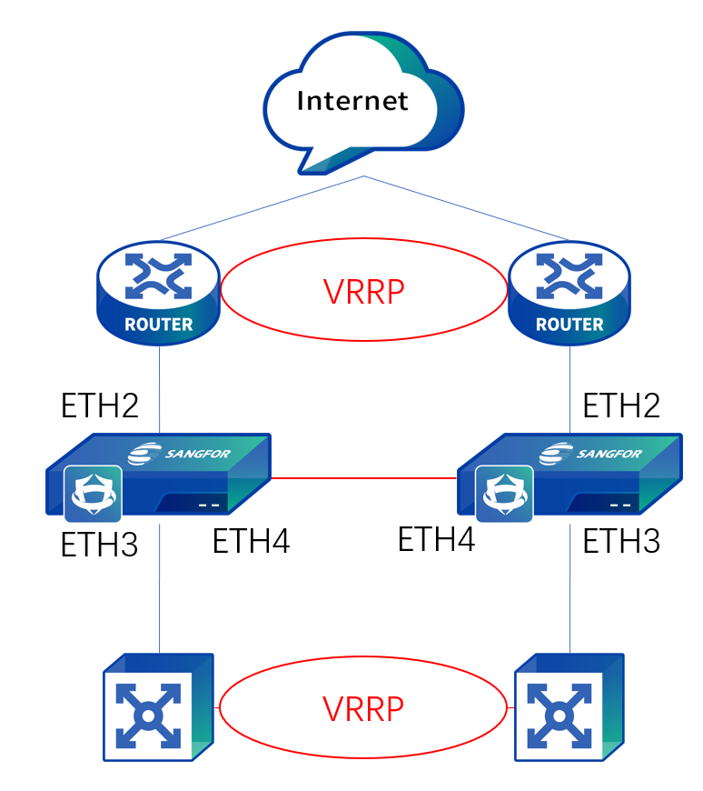
If an enterprise's LAN environment is VRRP and two NGAF devices are purchased and deployed in the network in virtual network cable mode, the two devices should be subject to dual-machine hot standby deployment. The specific topology is shown in the following figure.
Prerequisites
Configuration Steps
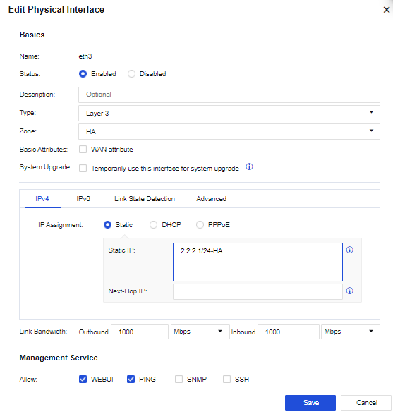
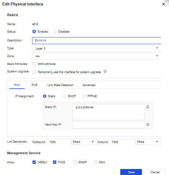
Step 1.Configure a heartbeat interface for the active device: Choose Network > Interfaces > Physical Interface, and select port eth3 to configure the IP address of the heartbeat interface. In this example, the IP address is set to 2.2.2.1/24-HA. See the figure below.
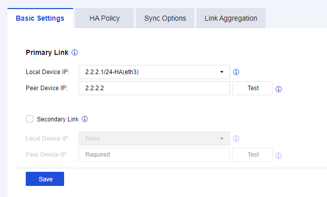
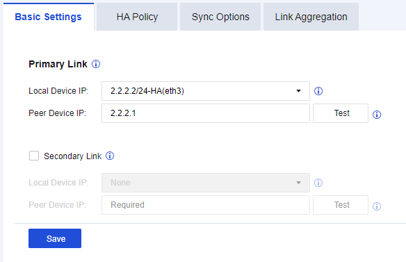
Step 2.Configure a heartbeat line for the active device: Go to the Basic Settings tab, and select eth4 for the Local Device IP parameter in the Primary Link section as the heartbeat interface. Set the Peer Device IP parameter to 2.2.2.2 as the IP address of the heartbeat interface. The Secondary Link parameter is not involved in this example. Suppose the heartbeat interface redundancy is required in the actual environment. In that case, an aggregate interface can be used as the heartbeat interface or select a routed interface in the second link as a secondary link heartbeat interface. The secondary link can synchronize only the heartbeat information. After the configuration is complete, click Save.
Step 3.Enable HA for the active device. Go to the HA Policy page, and select Enable.
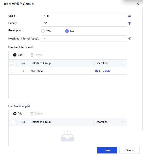
Step 4.Configure the HA information for the active device: On the HA Policy page, click Add to go to the Add Virtual Route Group page. When setting the Member Interface parameter, add ports eth1 and eth2 as two groups of monitoring ports and keep other settings unchanged. Click OK.

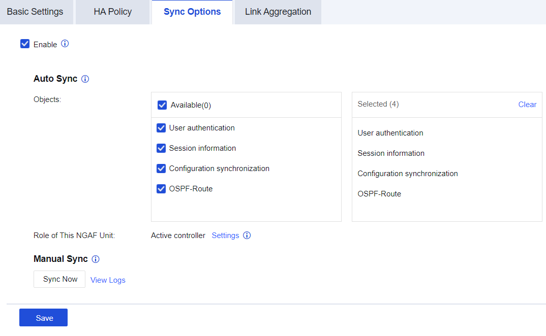
Step 5.Configure the synchronization information for the active device: Go to the Sync Options page and select Enable. Select all available objects for the Objects parameter and set the Role of This NGAF Unit parameter to Active controller. Then, click Save. See the figure below.
Step 6.Configure a heartbeat interface for the standby device: Choose Network > Interfaces > Physical Interface, and select port eth3 to configure the IP address of the heartbeat interface. In this example, the IP address is set to 2.2.2.2/24-HA. See the figure below.
Step 7.Configure a heartbeat line for the standby device. Go to the Basic Settings tab, and select eth4 for the Local Device IP parameter in the Primary Link section as the heartbeat interface. Set the Peer Device IP parameter to 2.2.2.1 as the IP address of the heartbeat interface. After the configuration is complete, click Save.
Step 8.Enable HA for the standby device. Go to the HA Policy page, and select Enable.
Step 9.Configure the HA standby information for the standby device. On the HA Policy page, click Add to go to the Add Virtual Route Group page. If the value of the Priority parameter is 50, which is lower than the value of the active device, add ports eth1 and eth2 as two groups of monitoring ports for the Member Interface parameter and keep other settings unchanged. Then, click Save.
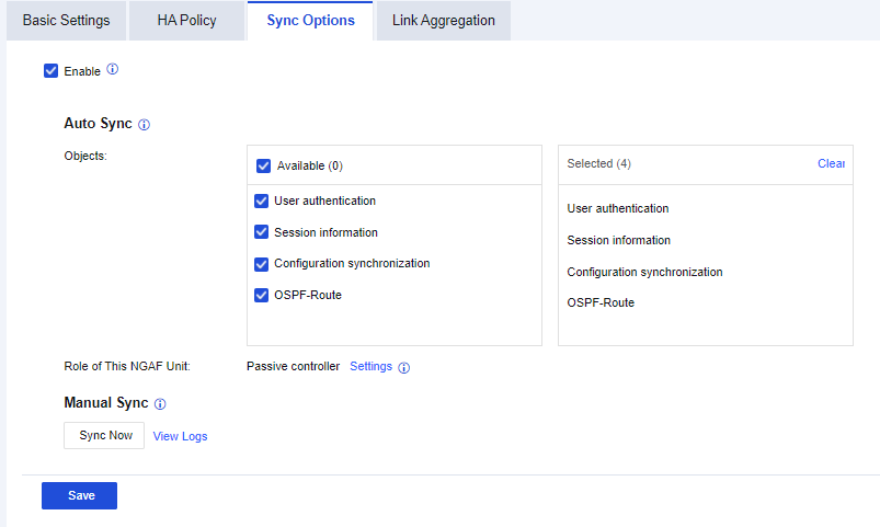
Step 10.Configure the synchronization information for the standby device. Go to the Sync Options page and select Enable. Select all available objects for the Objects parameter and set the Role of This NGAF Unit parameter to Passive controller. Then, click Save.
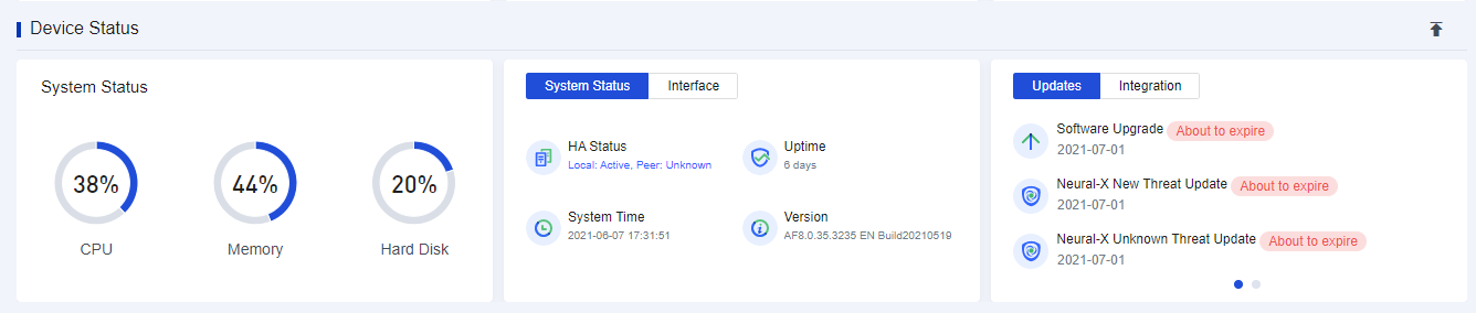
Step 11.After the active device and standby device are deployed in active-standby mode, power on the active device to connect the heartbeat line and other service lines. After the active device's NGAF is enabled, enable the standby device's NGAF to connect the heartbeat line and other service lines. After two devices are established, choose Home > Device Status to view the HA status.


 {{ $t('index.defaultHeader.chromeBrowserTip') }}