


{{ secondMenu.name }}




The DoS/DDoS attack (denial-of-service/distributed denial-of-service attack) generally aims at consuming server resources and forcing services to stop responding. The DoS/DDoS attack causes server response block by forging request data at a volume exceeding the server's handling capability so that normal user requests cannot get a response. The anti-DoS attack function of the NGAF device can be divided into two parts according to the attack direction: "inbound attack protection policy" and "outbound attack protection policy". This prevents DoS attacks from WAN to LAN and protects devices on the LAN from viruses or DoS attacks launched by using attack tools. You can add, delete, enable, disable, move up, move down, move, or refresh DDOS protection policies.
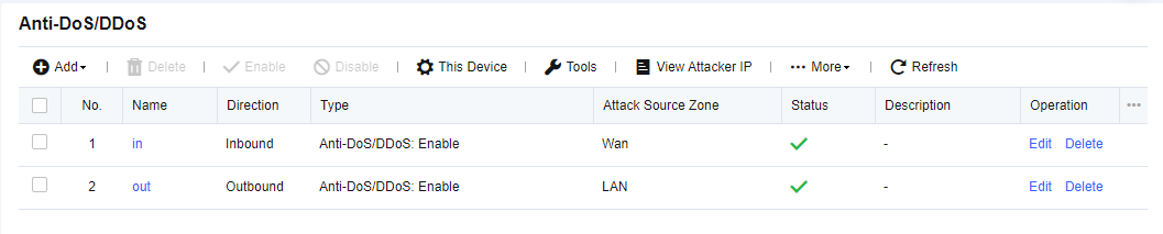
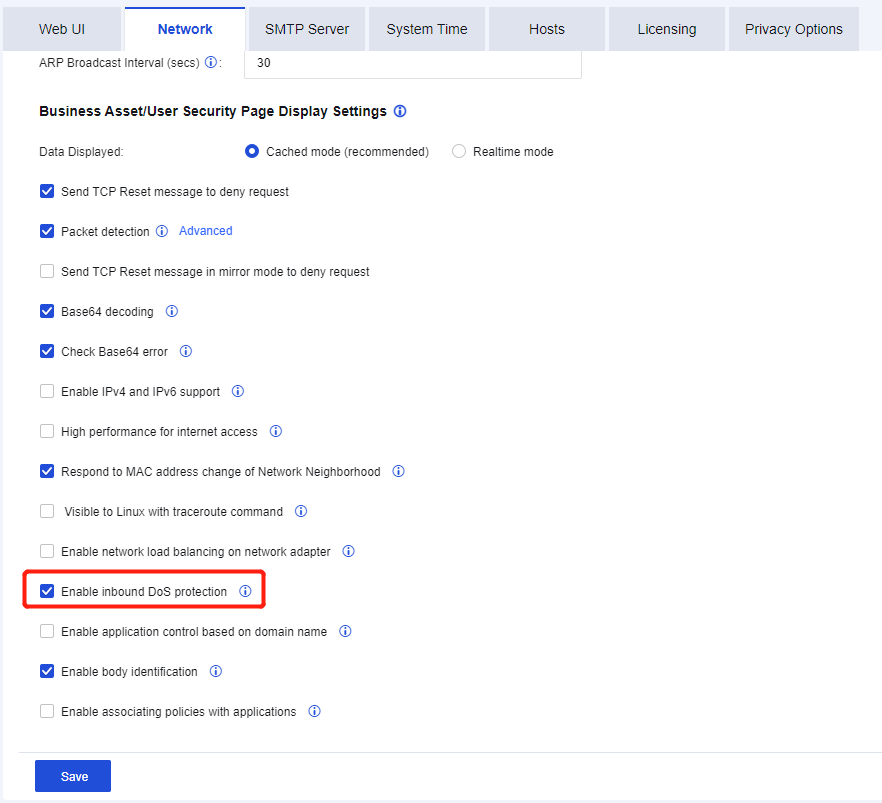
The WAN initiates DOS attacks on the LAN, which consume server resources and seriously affect business continuity. Therefore, DOS attacks on the WAN become a mainstream DOS attack means. By default, the inbound attack protection policy is disabled. To enable it, navigate to System > System Configuration > General Configuration > Network, as shown in the following figure.
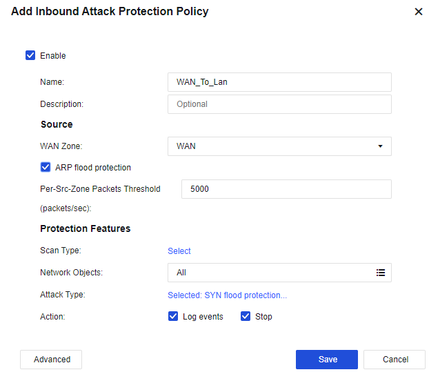
Click Add, and select Inbound Attack Protection Policy. Then, the Add Inbound Attack Protection Policy dialog box appears, as shown in the following figure.
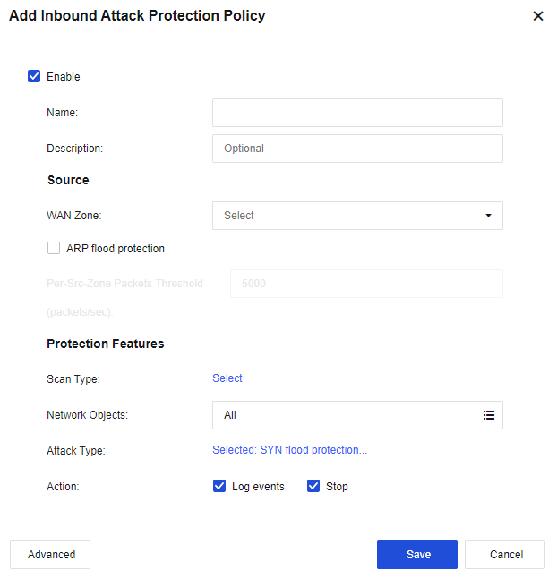
Name: Enter the name of the protection policy.
Description: Enter the description of the policy.
Source
WAN Zone: Select the source zone to be protected. The source zone of WAN protection is usually an external one.
ARP flood protection: Select this option to enable protection against ARP flood attacks. You can set the Per-Src-Zone Packets Threshold (packets/sec) parameter. If the interface of the zone receives more ARP packets per second than the threshold, it indicates that an attack has occurred. If you select Stop for the Action parameter in the lower part of the page, the ARP packets exceeding the threshold will be dropped after an attack is detected.
Protection Features
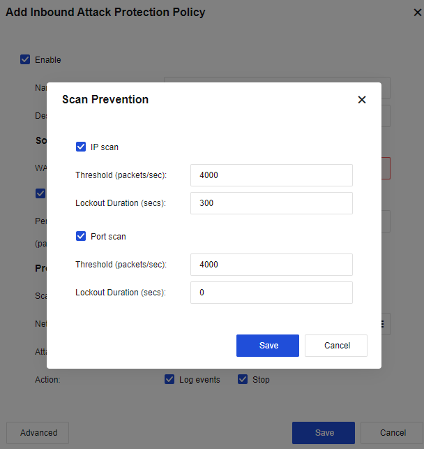
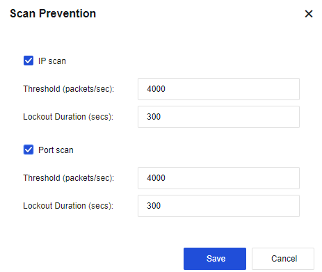
Scan Type: Select IP Scan and Port Scan. See the figure below.
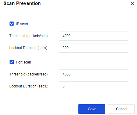
IP Scan: Enable this function and set the Threshold (packets/sec) parameter. If IP address scanning packets received from the source zone per second exceed the threshold, it indicates that an attack has occurred. If you select Stop for the Action parameter in the lower part of the page, all data of the source IP address will be blocked within 5 minutes after an attack is detected. The lockout will end in 5 minutes. The number of scanning packets of the IP address will then be calculated once again.
Port Scan: Enable this function and set the Threshold (packets/sec) parameter. If port scanning packets received from the source zone per second exceed the threshold, it indicates that an attack has occurred. If you select Stop for the Action parameter in the lower part of the page, all data of the source IP address will be blocked within 5 minutes after an attack is detected. The lockout will end in 5 minutes. The number of port scanning packets of the IP address will then be calculated once again.
Network Objects: Indicates the object to be protected, generally the destination IP address.
Attack Type: Click Selected: SYN flood protection… to set the respective thresholds for SYN Flood, UDP Flood, DNS Flood, and ICMP Flood, as shown in the following figure.
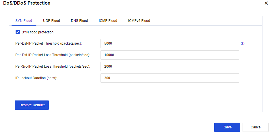
SYN Flood:
Per-Dst-IP Packet Threshold (packets/sec): Records the packets per second (PPS) of the SYN packets reaching each destination IP address. If the PPS exceeds the preset value, the NGFW SYN proxy mechanism will be triggered to release the server's load. We recommend setting this threshold lower than the packet loss threshold (half of the packet loss threshold is the best). Valid values: 1 to 100,000,000.
Per-Dst-IP Packet Loss Threshold (packets/sec): Records the PPS of the SYN packets reaching each destination IP address. If the PPS exceeds the preset value, the protection mechanism will be triggered. Valid values: 1 to 100,000,000.
Per-Src-IP Packet Loss Threshold (packets/sec): Records the PPS of the SYN packets reaching each source IP address. If the PPS exceeds the preset value, the protection mechanism will be triggered. Valid values: 1 to 100,000,000.
IP Lockout Duration (secs): Indicates the time after which lockout automatically starts when the PPS per source IP address exceeds the preset value. Valid values: 0 to 1,800 s. You can view attack IP addresses and lockout duration in the attacker list.
UDP Flood:
Per-Dst-IP Packet Loss Threshold (packets/sec): Records the PPS of the UDP packets reaching each destination IP address. If the PPS exceeds the preset value, the protection mechanism will be triggered. Valid values: 0 to 100,000,000.
Per-Src-IP Packet Loss Threshold (packets/sec): Records the PPS of the UDP packets reaching each source IP address. If the PPS exceeds the preset value, the protection mechanism will be triggered. Valid values: 0 to 100,000,000.
IP Lockout Duration (secs): Indicates the time after which lockout automatically starts when the PPS per destination IP address and the PPS per source IP address exceed the preset value. Valid values: 0 to 1,800 s. You can view attack IP addresses and lockout duration in the attacker list.
DNS Flood:
Per-Dst-IP Packet Loss Threshold (packets/sec): Records the PPS of the DNS packets reaching each destination IP address. If the PPS exceeds the preset value, the protection mechanism will be triggered. Valid values: 0 to 100,000,000.
Per-Src-IP Packet Loss Threshold (packets/sec): Records the PPS of the DNS packets reaching each source IP address. If the PPS exceeds the preset value, the protection mechanism will be triggered. Valid values: 0 to 100,000,000.
IP Lockout Duration (secs): Indicates the time after which lockout automatically starts when the PPS per destination IP address and the PPS per source IP address exceed the preset value. Valid values: 0 to 1,800 s. You can view attack IP addresses and lockout duration in the attacker list.
ICMP Flood:
Per-Dst-IP Packet Loss Threshold (packets/sec): Records the PPS of the ICMP packets reaching each destination IP address. If the PPS exceeds the preset value, the protection mechanism will be triggered. Valid values: 0 to 100,000,000.
Per-Src-IP Packet Loss Threshold (packets/sec): Records the PPS of the ICMP packets reaching each source IP address. If the PPS exceeds the preset value, the protection mechanism will be triggered. Valid values: 0 to 100,000,000.
IP Lockout Duration (secs): Indicates the time after which lockout automatically starts when the PPS per destination IP address and the PPS per source IP address exceed the preset value. Valid values: 0 to 1,800 s. You can view attack IP addresses and lockout duration in the attacker list.
ICMPv6 Flood:
Per-Dst-IP Packet Loss Threshold (packets/sec): Records the PPS of the ICMPv6 packets reaching each destination IP address. If the PPS exceeds the preset value, the protection mechanism will be triggered. Valid values: 0 to 100,000,000.
Per-Src-IP Packet Loss Threshold (packets/sec): Records the PPS of the ICMPv6 packets reaching each source IP address. If the PPS exceeds the preset value, the protection mechanism will be triggered. Valid values: 0 to 100,000,000.
IP Lockout Duration (secs): Indicates the time after which lockout automatically starts when the PPS per destination IP address and the PPS per source IP address exceed the preset value. Valid values: 0 to 1,800 s. You can view attack IP addresses and lockout duration in the attacker list.
Action: Select Log events and Stop.
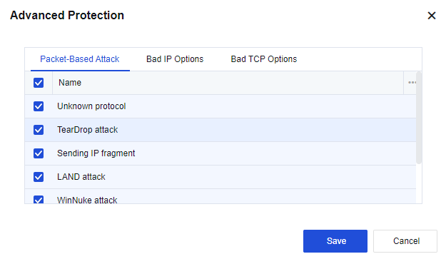
Click Advanced. Then, you can select options to enable the protection on the Packet-Based Attack, Bad IP Options, and Bad TCP Options tabs. By default, the options are not selected. See the figure below.
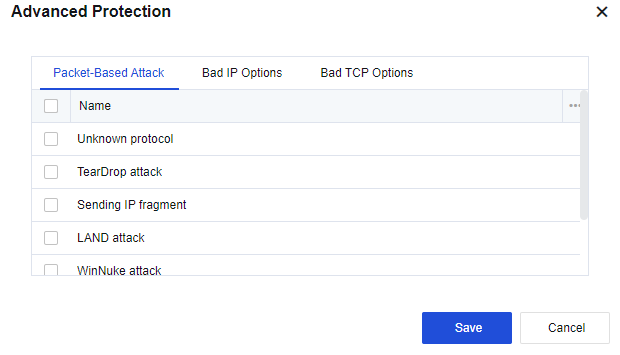
Packet-Based Attack
Unknown protocol: Select this option to enable the unknown protocol type protection. A protocol with an ID greater than 137 is considered to be an unknown protocol type.
TearDrop Attack: Select this option to enable TearDrop attack protection. Defense against TearDrop attacks is achieved by strict control over the fragment offset length of IP headers. If the fragment offset of an IP header does not comply with requirements, it indicates that a TearDrop attack has occurred.
Sending IP fragment: By default, the fragmented transmission of IP data blocks is not allowed. If the fragmented transmission occurs, it indicates that an attack has occurred.

We recommend you not to select this option unless it is a special case. Otherwise, the network connection may be interrupted.
LAND attack: Select this option to enable the LAND attack protection. If the device finds that the source and destination IP addresses of a packet are the same, the packet is considered a LAND attack.
WinNuke attack: Select this option to enable WinNuke attack protection. If a TCP packet header's URG flag bit is 1 and the destination port is TCP port 139 or TCP port 445, the packet is considered as a WinNuke attack.
Smurf attack: Select this option to enable the Smurf attack protection. If the device finds that the address responded by a packet is the ICMP response request packet of the broadcast address of the network, the packet is considered as a Smurf attack.
Oversized ICMP data attack: When an ICMP message is greater than 1024, it is considered an attack.
Bad IP Options
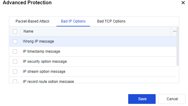
IP messages can generally include options such as IP timestamp message, IP security option message, IP stream option message, IP record route option message, IP loose source route option message, IP strict source route option message.
Common IP messages generally do not carry these additional options. IP messages with such options usually aim at attacking. If data messages are not allowed to carry these options, select the corresponding options for protection.
If you do not allow IP messages to carry unknown IP message options other than those listed above, select Wrong IP message.
Bad TCP Options
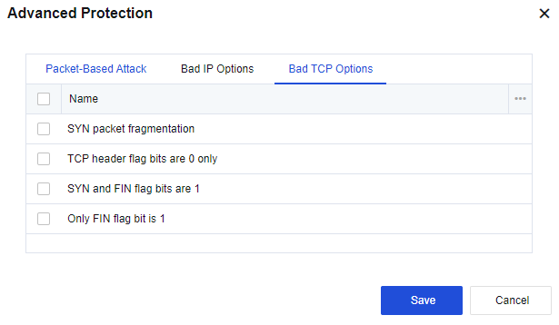
The Bad TCP Options tab includes the following options: SYN packet fragmentation, TCP header flag bits are 0 only, SYN and FIN flag bits are 1, and Only FIN flag bit is 1. In general, normal TCP message flags will never have these features and the target host may be unable to handle TCP messages with these features and thus become abnormal. If you select the options, the device will protect against messages with the corresponding features.
Finally, click Save to save the settings of the inbound attack protection policy.
To add more inbound attack protection policies, click Add.
To modify an existing inbound attack protection policy, click the name of the policy.
To delete a policy, select the policy and click Delete in the Operation column.
Click Enable to enable the policy.
Click Disable to disable the policy.
Click Move Up or Move Down to adjust the order of the policy.
For policy matching, the policy in the higher position will be matched first.
1. Data packet matching is conducted from the top down and will stop after a packet matches an attack activity and is dropped. A data packet continues to check whether it matches the set attack activities until it matches one.
2. If you have set scanning protection, it is good to set the information as well, such as ICMP Flood in the DoS/DDoS Attack Protection dialog box.
The intrusion of a hacker generally begins by scanning whether IP addresses exist. If so, the hacker continues to scan ports. The hack will proceed to the next attack activity after the IP address and port are discovered. Some hackers may already know the IP addresses and ports and directly initiate attacks without performing scanning. Therefore, it is better to set both protection options for effective protection against attack activities.
The server of an enterprise often suffers from slow service access, and some resources of the server are highly used. Packet capture reveals that this phenomenon is caused by sending a large number of SYN packets, UDP packets, etc., to some internet IP addresses and occupying many resources. Therefore, you need to configure DDOS attack protection for NGAF deployed at the internet egress to solve this problem.
Step 1.Click Add, and select Inbound Attack Protection Policy. Then, the Add Inbound Attack Protection Policy dialog box appears, as shown in the following figure.
Step 2.Click Selected: IP Scan, Port scan to enable Scan Prevention, as shown in the following figure.
Step 3.Select the network object to protect the specific IP. If no specific IP address is required, select All.
Step 4.Click Selected: SYN flood protection to configure DoS/DDoS attack protection, as shown in the following figure.
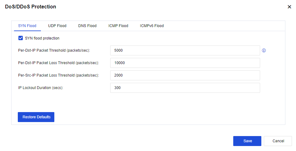
Set the SYN Flood, UDP Flood, DNS Flood, ICMP Flood, and ICMPv6 Flood parameters according to actual requirements.
Step 5.Optional. Click Advanced to select protection options against specific attacks, as shown in the following figure.
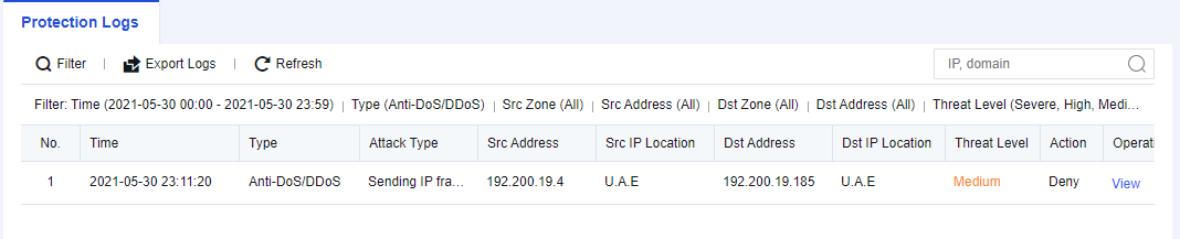
Step 6.The test results are shown in the following figures.
The outbound attack protection prevents the LAN host from becoming a zombie to attack the WAN, thus bringing certain legal risks.
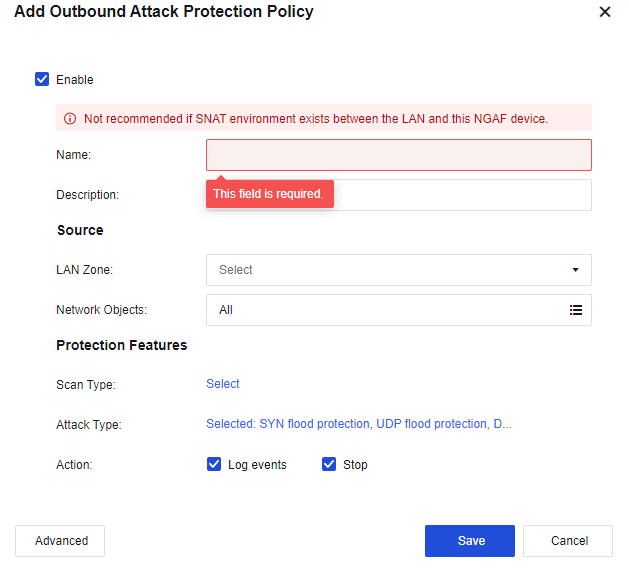
In the office network environment of an enterprise, it is often found in the internet egress that several PCs often use excessive bandwidth, resulting in the slow speed of the LAN network. If you log in to the PC for viewing, you will find that it sends SYN and UDP messages to an IP address all the time. To prevent this recurrence, you need to add an outbound attack protection policy on the NGAF.
Step 1.Click Add, and select Outbound Attack Protection Policy. Then, the Add Outbound Attack Protection Policy dialog box appears, as shown in the following figure.
Step 2.Click Selected: IP Scan, Port scan to enable Scan Prevention, as shown in the following figure.
Step 3.Click Selected: SYN flood protection to configure DoS/DDoS attack protection, as shown in the following figure.
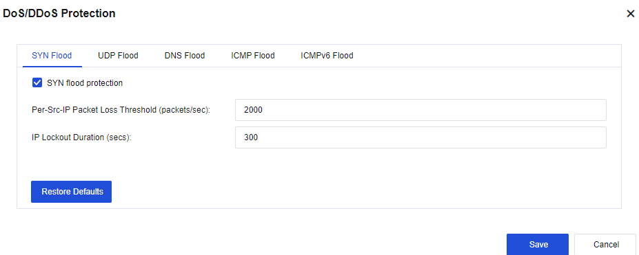
Set the SYN Flood, UDP Flood, DNS Flood, ICMP Flood, and ICMPv6 Flood parameters according to actual requirements.
Step 4.Optional. Click Advanced to select protection options against specific attacks, as shown in the following figure.

Step 5.The configuration results are shown in the following figure.

Step 6.The attack effect is shown in the following figures.

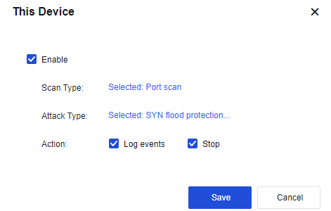
Local DoS protection is to defend against attacks aimed at the NGAF device itself. Click This Device to set the protection type, as shown in the following figure.
Tools in Anti Dos Protection are used for setting regional access control, LAN access control, and DoS exclusion, as shown in the following figure.
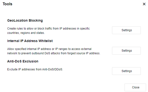
GeoLocation Blocking: Rejects or allows IP traffic of the specified countries or regions. Click Settings. Then, the GeoLocation Blocking dialog box appears.
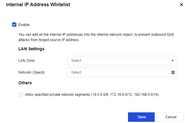
Internal IP Address Whitelist: Configures to only allow the outbound access of the specified IP addresses or IP address ranges on the LAN. Click Settings. Then, the Internal IP Address Whitelist dialog box appears, as shown in the following figure.
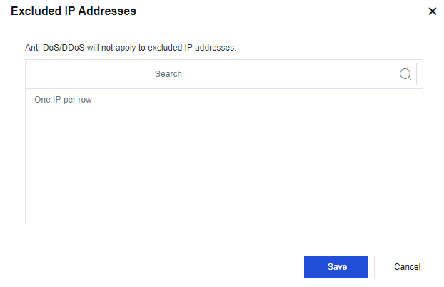
Anti-DoS Exclusion: Specify IP addresses to be excluded from the DoS/DDoS protection, as shown in the following figure.
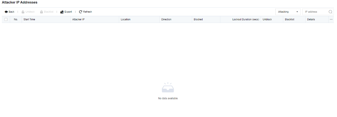
Click View to go to the Attacker IP Addresses page, on which you can view the details such as IP addresses of active attackers or those in the last 7 days.


 {{ $t('index.defaultHeader.chromeBrowserTip') }}