


{{ secondMenu.name }}




IPv4 NAT is applied for IPv4 environments to perform NAT translation for IPv4 addresses, including Source NAT, Destination NAT, and Bidirectional NAT. Administrators can perform the following IPv4 NAT operations.
| Operation |
Note |
| Delete |
Deletes the checked policy |
| Enable/Disable |
Enables or disable the checked policy |
| Move |
Moves positions of policies to adjust the priority. The policy that topped the list has the highest priority |
| Clear matches |
Clear the matching data of the selected policy and return it to 0 |
| Simulation matching |
Simulates the source and destination data packets to see if they match the relevant policies |
| Import/Export |
Supports policy import or export |
| Refresh |
Refreshes the page to display the latest data |
| Search keywords |
Searches by policy name |
Table 10:Description of IPv4 NAT Parameters
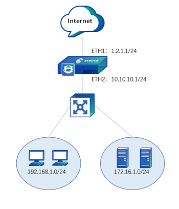
The following topology is used in all examples in this section: The LAN user-side network segment is 192.168.1.0/24, the server-side network segment is 172.16.1.0/24, NGAF is deployed at the internet egress as a gateway, the IP address of ETH1 interface is 1.2.1.1/24, and the IP address of ETH2 interface is 10.10.10.1, as shown in the following figure.
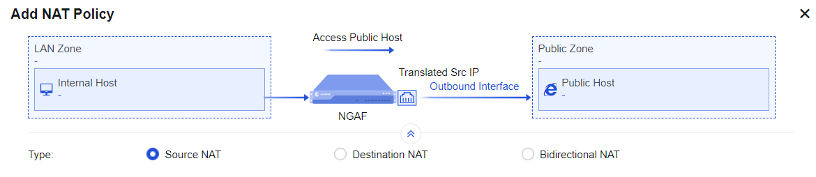
To translate the source IP address of data that meets translation conditions. In the most common scenarios, when the device is deployed at the internet egress and acts as a proxy for LAN users to access the internet, you must add a SNAT policy to translate the source IP address. On the IPv4 NAT page, you can manage, add, or delete a SNAT policy. The SNAT process is shown in the following figure.
If an enterprise needs to enable both LAN users and server groups to access the internet through NGAF, you must add a SNAT policy on the NGAF device. In this way, when data that is generated by accessing the internet through the network segments192.168.1.0/24 and 172.16.1.0/24 passes through NGAF, its IP address can be translated into 1.2.1.1, that is, the IP address of the NGAF device's egress interface ETH1.
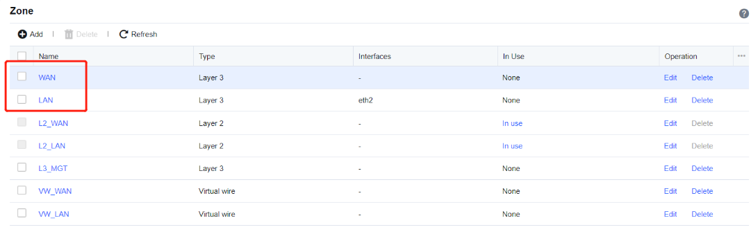
Step 1.Define LAN and WAN zones. Before you add a SNAT policy, navigate to Network > Interfaces > Zone and select the zone to which the interface belongs on the Zone page. Then, navigate to Objects > Network Objects and select the IP address group to which the LAN segment belongs. In this example, select WAN for the ETH1 interface and LAN for the ETH2 interface, and define the network segments 172.16.1.0/24 and 192.168.1.0/24 as Internal on the Network Objects tab.

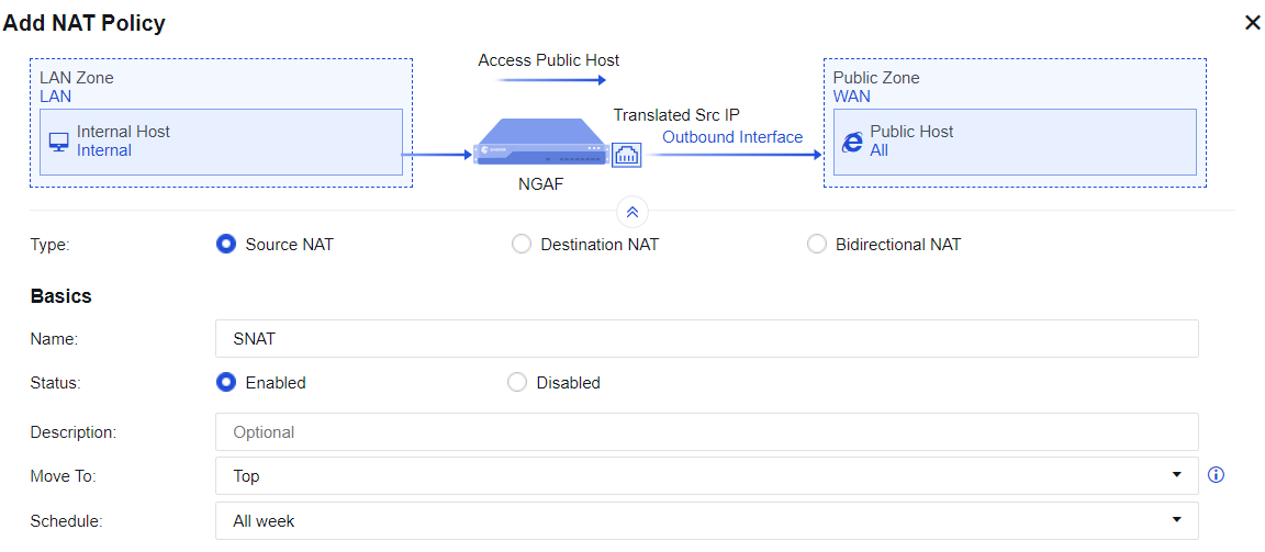
Step 2.Add a NAT policy. Navigate to NAT > IPv4 NAT and click Add. Then, the Add NAT Policy dialog box appears. By default, Source NAT is selected. In the Basics section, enter the name of the policy in the Name field, enter a custom description in the Description field, and specify the Move To and Schedule parameters.
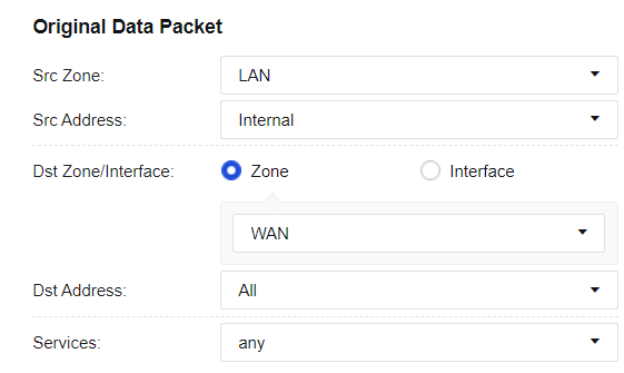
Step 3.Set an original data packet to comply with the policy.
• Src Zone and Src Address: Select the source IP address for which a SNAT policy is added. This is because only data from the specified source zone and specified source IP address can match this policy to enable SNAT. If the routing interface acts as a proxy for LAN users to access the internet, you can set the Src Zone parameter to LAN and the Src Address parameter to Internal or All. In this example, select LAN for the Src Zone parameter and Internal for the Src Address parameter.
• Dst Zone/Interface and Dst Address: Set destination data that complies with the policy, such as data to the specified destination zone, accessing the specified destination IP address group, and outgoing from the specified interface. If the routing interface acts as a proxy for LAN users to access the internet, you can set the Dst Zone/Interface parameter to WAN and the Dst Address parameter to All. In this example, select WAN for the Dst Zone/Interface parameter and All for the Dst Address parameter.
• Services: Set this parameter if SNAT is set only for the data conforming to the specified protocol, source port, and destination port. To set this parameter, click the drop-down list. In this example, you do not need to set this parameter, and any is selected by default.
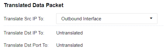
Step 4.Set a translated data package. If you select Source NAT for Type, set a specified IP address to which the source IP address of data conforming to the specified source IP address, destination IP address, and service is translated. You can select Outbound Interface, IP Range, IP Address, Network Objects, or Untranslated for the Translate Src IP To parameter. In this example, select Outbound Interface from the drop-down list.
Step 5.Save the configuration. Finally, click Save. Then, the configuration of the SNAT policy is complete.

Step 6.After the application control strategy from the LAN to the WAN is allowed, use a PC in the LAN segment to normally access the WAN.
To translate the destination IP address of data passing through the device. This function is often used to publish servers by mapping the services of LAN servers to the internet so that internet users can access internal servers through the public IP address. The following figure shows the destination NAT configuration page.
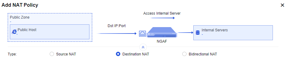
There is a web server 172.16.1.100 on port 80 of an enterprise's intranet to provide HTTP service and has applied for a domain name www.xxx.com to point to 1.2.1.1. The customer hopes that external users can enter http://www.xxx.com to access the LAN 172.16.1.100 server.
Step 1.Define LAN and WAN zones. Before you add a DNAT policy, navigate to Network > Interfaces > Zone and select the zone to which the interface belongs on the Zone page. In this example, select WAN for the ETH2 interface and LAN for the ETH1 interface.
Step 2.Add a NAT policy. Navigate to NAT > IPv4 NAT and click Add. Then, the Add NAT Policy dialog box appears. Select Destination NAT, and enter the name of the policy in the Name field, enter a custom description in the Description field, and specify the Move To and Schedule parameters in the Basics section.
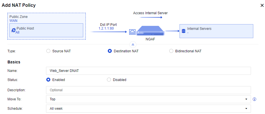
Step 3.Set an original data packet to comply with the policy.
Src Zone: Specify the zone from which the data entering the device is subject to DNAT. For example, when a LAN server is published to the internet, internet users can access the server and this parameter is set to WAN.
Src Address: Specify the source IP address only from which data to be subject to DNAT comes.
Destination: Specify the IP address that DNAT is performed when internet users access this address. The destination IP address is the IP address accessed by users before DNAT for a data packet and is usually the public IP address of a device interface. In this example, this parameter is set to 1.2.1.1.
Services: Set the service for which DNAT is to be performed. In this example, select HTTP for this parameter. The service can be added directly or defined in the network object.
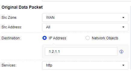
Step 4.Set conditions of a translated data packet.
IP Address: Specify the IP address to which the destination IP address is translated, and choose whether to translate the destination port or not. In this example, set the IP address of the LAN server that provides HTTP services to 172.16.1.100, the Translate Dst IP To parameter to IP Address, and the Translate Port To parameter to Untranslated.
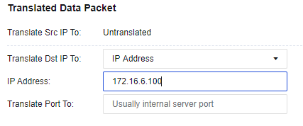

If you need to map port 80 in the network segment 1.2.1.1 to port 8080 of the servers in the LAN segment 172.16.1.100, you can set Translate Port To to port 8080
Step 5.Allow an application control policy. By default, Allow Background ACL is selected for the Allow Policy parameter. This function automatically allows all traffic matching this policy at the application control level to pass. If this option is not selected, you need to configure the application control policy to enable the traffic to pass. Finally, click Save. Then, the configuration is complete. See the figure below.

Step 6.External users can access LAN server 172.16.1.100 via http://www.xxx.com
To translate the source IP address and destination IP address of data passing through the device. This function is often used to publish servers by mapping the services of LAN servers to the internet so that external and internal users can access internal servers through the public IP address. The following figure shows the bidirectional NAT configuration page.
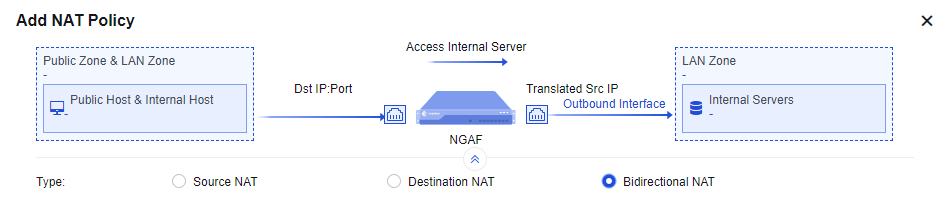
An enterprise uses port 80 of a web server in the LAN segment 172.16.1.100 to provide HTTP services and has applied for a domain name www.xxx.com bound to the IP address 1.2.1.1. The customer hopes that external users can enter http://www.xxx.com to access the LAN 172.16.1.100 server, and the LAN users can also access the LAN 172.16.1.100 server by visiting http:// www.xxx.com. Here, a bidirectional NAT policy is required.
Step 1.Define LAN and WAN zones. Before you add a DNAT policy, navigate to Network > Interfaces > Zone and select the zone to which the interface belongs on the Zone page. In this example, select LAN for the ETH2 interface and WAN for the ETH1 interface.
Step 2.Add a NAT policy. Navigate to NAT > IPv4 NAT and click Add. Then, the Add NAT Policy dialog box appears. Select Bidirectional NAT, enter the name of the policy in the Name field and custom description in the Description field, and specify the Move To and Schedule parameters in the Basics section.
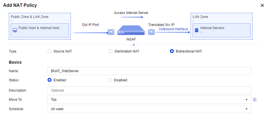
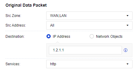
Step 3.Set an original data packet to comply with the policy.
Src Zone: Specify the zone from which the data entering the device is subject to BNAT. For example, when a LAN server is published to the internet, internet users can access the server, and LAN users can also access the server by using the public domain name. In this case, this parameter is set to WAN and LAN.
Src Address: Specify the source IP address only from which data to be subject to BNAT comes.
Destination: Specify the IP address that BNAT is performed when internet users access this address. The destination IP address is the IP address accessed by users before BNAT for a data packet and is usually the public IP address of a device interface. In this example, this parameter is set to 1.2.1.1.
Services: Set the service for which BNAT is to be performed. In this example, select HTTP for this parameter. The service can be added directly or defined in the network object.
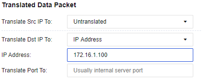
Step 4.Set conditions of a translated data packet.
IP Address: Specify the IP address to which the destination IP address is translated, and whether to translate the destination port or not. In this example, set the IP address of the LAN server that provides HTTP services to 172.16.1.100, the Translate Dst IP To parameter to IP Address, and the Translate Port To parameter to Untranslated.
Step 5.By default, Allow Background ACL is selected for the Allow Policy parameter. This function automatically allows all traffic matching this policy at the application control level to pass. If this option is not selected, you need to configure the application control policy to enable the traffic to pass. Finally, click Save. Then, the configuration is complete. See the figure below.

Step 6.Both the external and internal users can access the server in the LAN segment 172.16.1.100 by visiting http:// www.xxx.com.


 {{ $t('index.defaultHeader.chromeBrowserTip') }}