


{{ secondMenu.name }}




Virtual network cable deployment is another particular case of transparent deployment and is similar to transparent deployment. The difference between them lies in:
The interface is also a layer 2 interface, but it is defined as a virtual cable interface:
• The virtual network interfaces must be in pairs. When forwarding data, it does not need to check the MAC table and directly forwards it from the interface paired with virtual network cable;
• The forwarding performance of the virtual network cable is higher than that of the transparent interface, so it is recommended to deploy using the virtual cable interface in a general network bridge environment;
• The deployment of virtual network cable has occupied two interfaces. Hence, to connect a management device, another interface should be selected.
Deployment Case of Virtual Network Cable Mode
The network environment of an enterprise is shown below. There are two layer 3 switch and two routers in the LAN for load balancing. This enterprise wants to deploy the NGAF device transparently on the website, but does not want to change the original Internet access mode. In this case, two-layer isolation must be provided between eth4 & eth2 networking interfaces and eth1 & eth3 networking interfaces. In other words, the data transmitted to eth4 must be forwarded from eth2, and that transmitted to eth1 must be forwarded from eth3, which can be realized through configuring a virtual cable interface.
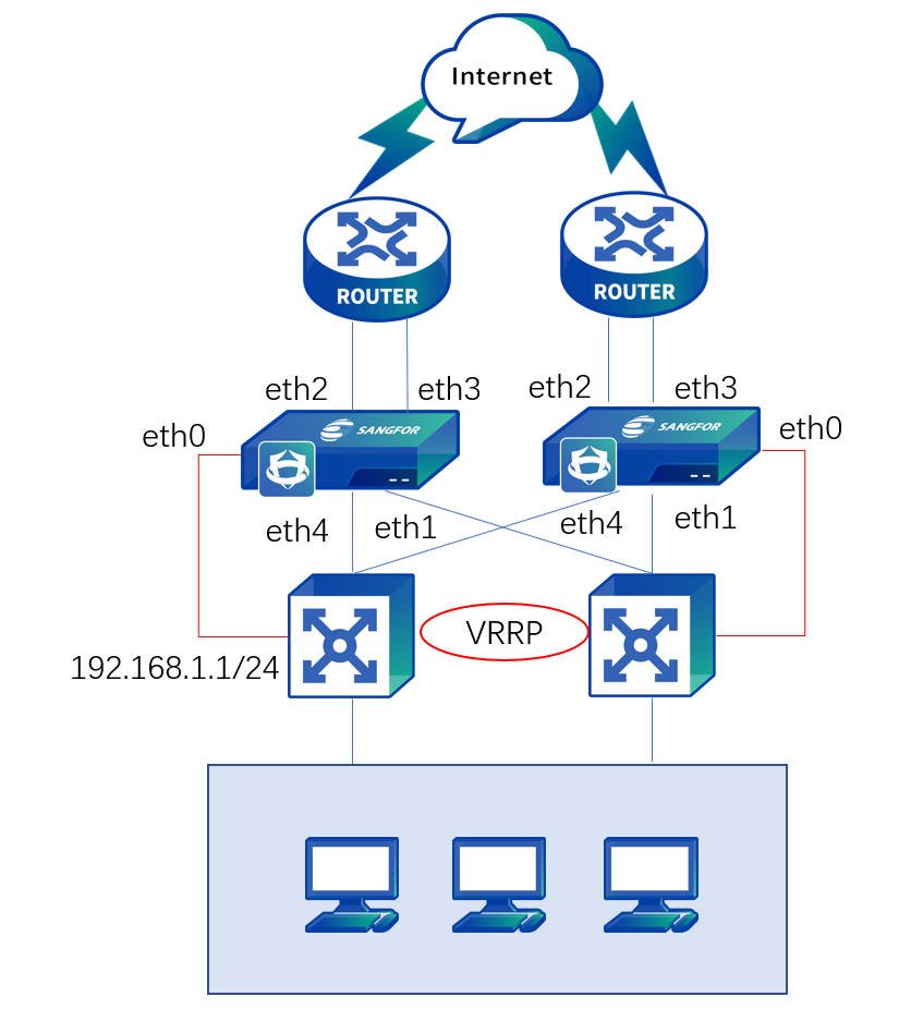
The deployment methods of the two NGAF devices are the same. We have illustrated the steps by taking one as an example.
Step 1.Log in to the device through the default IP address of the management interface (ETH0). The default IP address of the management interface is 10.251.251.251/24. You need to configure an IP address in the same network segment on the computer and log in to the device via https://10.251.251.251.
Step 2.On the Network > Interfaces > Physical Interface page, click the interface to be set as a WAN interface. Select eth2 as the uplink WAN interface, and select the virtual network cable type and the custom uplink zone, as shown below.
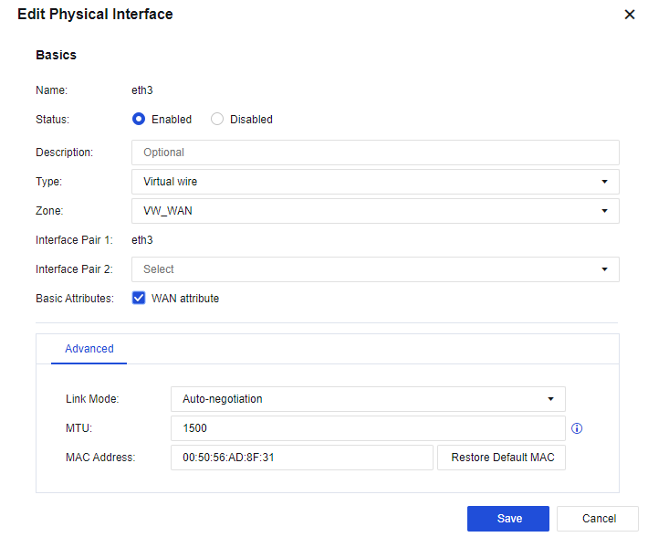
Step 3.On the Network > Interfaces > Physical Interface page, click an interface and set it as a LAN interface. Select eth4 as the downlink LAN interface, select the virtual network cable type and the custom downlink zone, and set eth2 defined in step 1 for Interface Pair 2, as shown below.
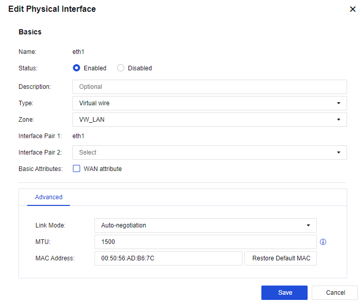
Step 4.Configure eth1 and eth3 interfaces according to the method described in steps 2 and 3.
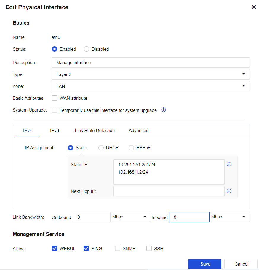
Step 5.Configure the management interface. On the Network > Interfaces > Physical Interface page, select eth0 as the management interface. Do not modify the default IP address of eth0 10.251.251.251/24. Add an IP address belonging to the same network segment as that of the LAN switch as the management IP address so that the LAN administrator can conveniently manage the device.
Step 6.In this case, to realize active and standby switching between LAN switches and routers, enable interface correlation on Network > Interfaces > Link State Propagation page. Check the Enable correlation of interfaces in LINK state on the Network > Interfaces > Link State Propagation page, and select eth1 & eth3 and eth2 & eth4 for interface correlation, as shown below.
Step 7.Configure a route: You need to configure a default route to 0.0.0.0/0.0.0.0, pointing to the LAN switch 192.168.1.1. Then, go to the Network > Route > Static Route page and click Add to add a static route. Specifically, configure the default routing Dst IP/Netmask as 0.0.0.0/0 and the Next-Hop IP as 192.168.1.1. See the figure below.
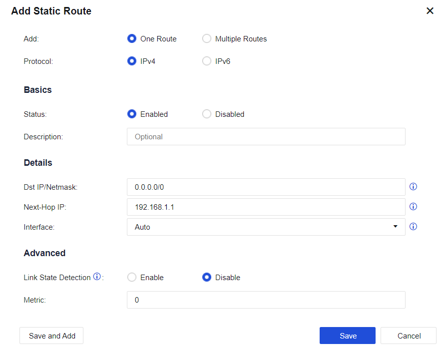
Step 8.Configure the application control policy: Assign the Internet access permissions to LAN users. On the Policies > Access Control > Application Control Policy page, add an application control policy, and assign the LAN-WAN data access permissions. Then, on the displayed page, select the custom downlink zone as the Src Zone, the custom LAN address as Src Address, the custom uplink zone as Dst Zone, All in Dst Address, any in Services, and All in Applications respectively.
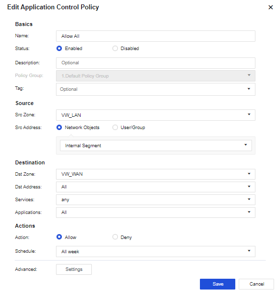
Step 9.After completing the basic configuration, connect the device to the network, eth2 and eth3 interfaces to the preceding router, and eth1 and eth4 interfaces to the two-layer 3 LAN switches respectively.


 {{ $t('index.defaultHeader.chromeBrowserTip') }}