


{{ secondMenu.name }}




When the data-transmitting networking interface of the NGAF device is in the transparent interface mode, the device is basically deployed in the transparent mode and regarded as a network cable with a filtering function. This deployment mode is used when it is inconvenient to change the original network topology. The device is connected between the original gateway and LAN users without changing the gateway and LAN users' configuration.
After some basic configurations are completed on the NGAF device, this deployment mode is ready. The main feature of the transparent mode is that it is entirely transparent to users. Transparent interfaces include the Access interface and the Trunk interface.
Deployment Case of Access Interface in Transparent Mode
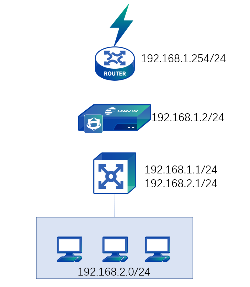
There is a layer 3 enterprise network and routers are deployed at the Internet port. As the original environment cannot be changed, the NGAF device needs to be transparently deployed on the network, as shown below.
Step 1.Log in to the device through the default IP address of the management interface (ETH0). The default IP address of the management interface is 10.251.251.251/24. You need to configure an IP address in the same network segment on the computer and log in to the device via https://10.251.251.251.
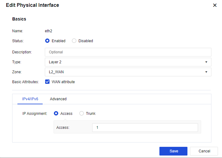
Step 2.On the Network > Interfaces > Physical Interface page, click the interface to be set as a WAN interface. Select eth2 as the uplink WAN interface, select the transparent type and the custom uplink zone, check the WAN attribute option, and set IP Assignment to Access 1, as shown below.
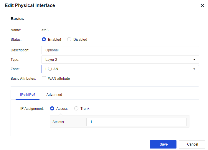
Step 3.On the Network > Interfaces > Physical Interface page, click the interface to be set as a LAN interface. Select eth3 as the downlink LAN interface, select the transparent type and the custom downlink zone, and set IP Assignment to Access 1, as shown below.
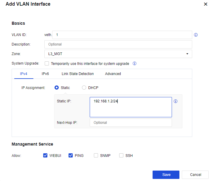
Step 4.Configure the management interface: On the Network > Interfaces > VLAN Interface, configure the logic interface of the VLAN interface as the management interface, set the VLAN ID field to 1, and assign a management IP address 192.168.1.2/24. See the figure below.
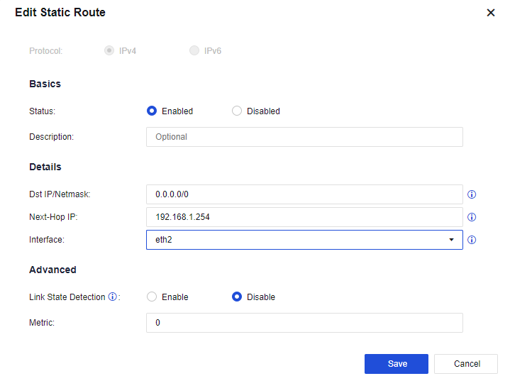
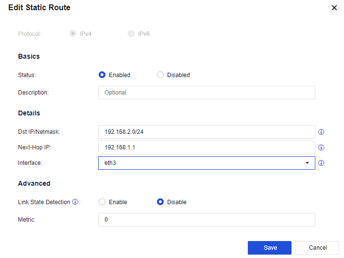
Step 5.Configure a route: You need to configure a default route to 0.0.0.0/0.0.0.0 pointing to the pre-gateway 192.168.1.254. Meanwhile, in this case, as the LAN interface is connected to multiple network segments spanning three layers, you need to configure another static route containing each network segment to the layer 3 switch. Go to the Network > Route > Static Route page and click Add to add a static route. Specifically, configure the default routing Dst IP/Netmask as 0.0.0.0/0 and the Next-Hop IP as 192.168.1.254, and configure the backhaul routing Dst IP/Netmask as 192.168.2.0/24 and the Next-Hop IP as 192.168.1.1. See the figure below.
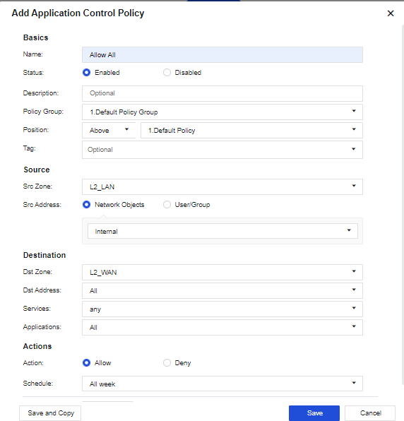
Step 6.Configure the application control policy: Assign the Internet access permissions to LAN users. On the Policies > Access Control > Application Control Policy page, add an application control policy, and assign the LAN-WAN data access permissions. Then, on the displayed page, select the custom downlink zone as the Src Zone, the custom LAN address as Src Address, the custom uplink zone as Dst Zone, All in Dst Address, any in Services, and All in Applications respectively.
Step 7.After completing the basic configuration, connect the device to the network, eth2 interface to the preceding router, and eth3 interface to the layer 3 LAN switch.
Deployment Case of Trunk Interface in Transparent Mode
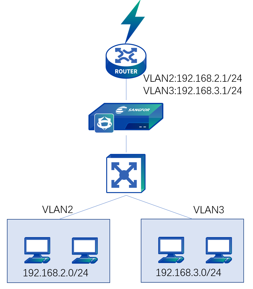
The users' network topology is shown in the figure below.
The device is deployed in transparent mode. The VLAN is configured for the LAN switch but the routing function is disabled. The preceding router serves as the gateway of each VLAN. The LAN segments include 192.168.2.0/255.255.255.0 and 192.168.3.0/255.255.255.0, belonging to VLAN2 and VLAN3 respectively. The TRUNK protocol works between the switch and the router.
Step 1.You need to log in to the device through the default IP address of the management interface (ETH0). The default IP address of the management interface is 10.251.251.251/24. You need to configure an IP address in the same network segment on the computer and log in to the device via https://10.251.251.251.
Step 2.On the Network > Interfaces > Physical Interface page, click the interface to be set as a WAN interface. Select eth2 as the uplink WAN interface, select the transparent type and the custom uplink zone, check the WAN attribute option, and set IP Assignment to Trunk, as shown below.
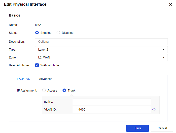
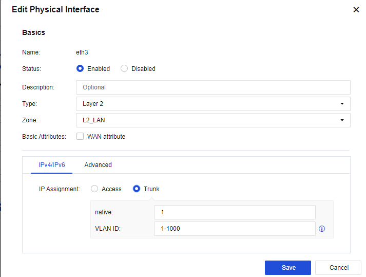
Step 3.Step 3. On the Network > Interfaces > Physical Interface page, click the interface to be set as a LAN interface. Select eth3 as the downlink LAN interface, select the transparent type and the custom downlink zone, and set IP Assignment to Trunk, as shown below.
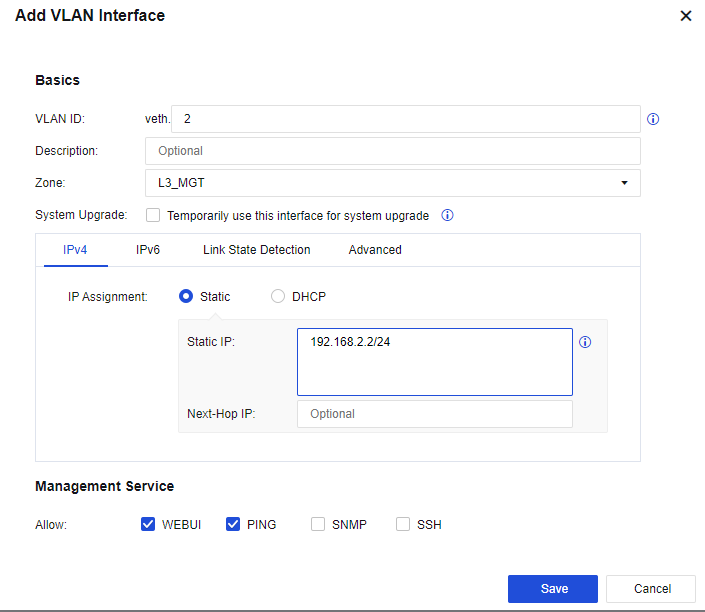
Step 4.Configure the management interface: On the Network > Interfaces > VLAN Interface, configure the logic interface of the VLAN interface as the management interface, set the VLAN ID field to 2, and assign a management IP address 192.168.2.2/24. See the figure below.
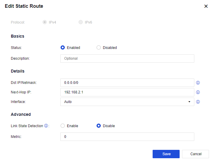
Step 5.Configure a route: You need to configure a default route to 0.0.0.0/0.0.0.0, pointing to the pre-gateway 192.168.2.1 that belongs to the same network segment as the management IP address. Then, go to the Network > Route > Static Route page and click Add to add a static route. Specifically, configure the default routing Dst IP/Netmask as 0.0.0.0/0 and the Next-Hop IP as 192.168.2.1, as shown below.
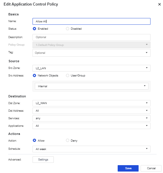
Step 6.Configure the application control policy: Assign the Internet access permissions to LAN users. On the Policies > Access Control > Application Control Policy page, add an application control policy, and assign the LAN-WAN data access permissions. Then, on the displayed page, select the custom downlink zone as the Src Zone, the custom LAN address as Src Address, the custom uplink zone as Dst Zone, All in Dst Address, any in Services, and All in Applications respectively.
Step 7.After completing the basic configuration, connect the device to the network, eth2 interface to the preceding router, and eth3 interface to the two-layer LAN switch.


 {{ $t('index.defaultHeader.chromeBrowserTip') }}