


{{ secondMenu.name }}




A typical application environment for routing deployment is to deploy an NGAF device in the routing mode at the Internet port as a proxy of the LAN. The device is deployed like a router in the network. The WAN port is connected to the ADSL dial-up or Internet line while the LAN port to the LAN switch.
Deployment Case of Routing Mode
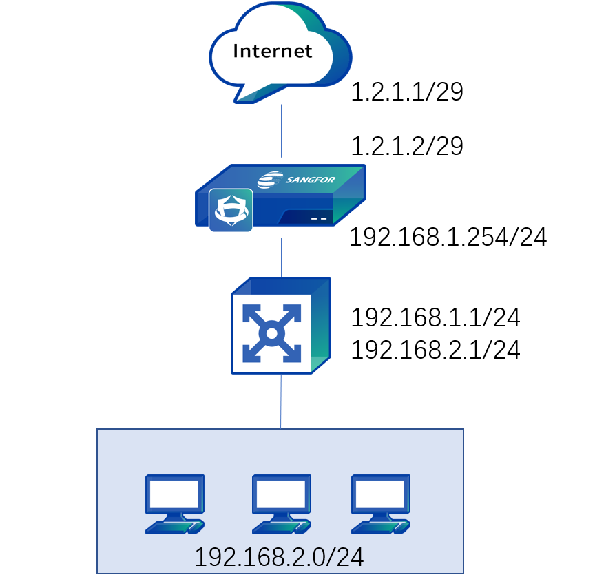
An enterprise network is a layer 3 environment. It is planned to deploy the NGAF device at the Internet port as a proxy of the LAN. The Internet line is connected to the fixed IP address via optical fiber, as shown below.
Step 1.Log in to the device through the default IP address of the management interface (ETH0). The default IP address of the management interface is 10.251.251.251/24. You need to configure an IP address in the same network segment on the computer and log in to the device via https://10.251.251.251.
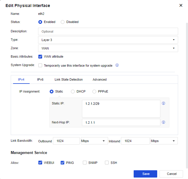
Step 6. Configure the WAN interface: Click the interface to be set as the WAN interface through Network > Interfaces > Zone. Select eth2 as the WAN interface, select the route Type and the custom WAN in Zone, check the WAN attribute option and configure an IP address 1.2.1.2/29 and the next-hop address 1.2.1.1, etc. See the figure below.

1.The next-hop gateway of an interface is only applied to the link detection and policy-based routing functions. Setting the next-hop gateway does not generate a 0.0.0.0/0 default route on the device. Thereby, you need to configure the default route.
2.The line bandwidth setting of an interface is not associated with traffic management, and the line bandwidth setting at the interface is used for scheduling policy-based routing.
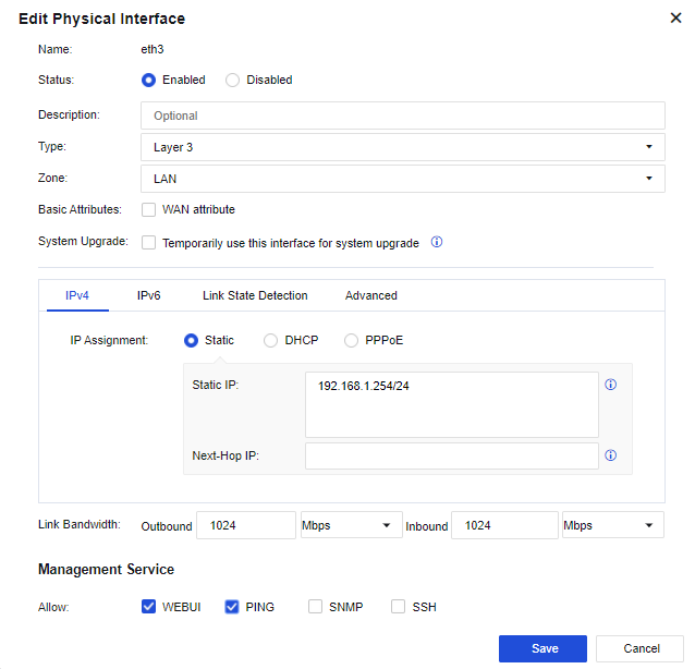
Step 2.Configure the LAN interface: Select an idle networking interface and click on the interface name to go to the configuration page. Then, select eth3 as the LAN interface, select the routing type and the user-defined LAN area, and configure an IP address 192.168.1.254/24, as shown below.
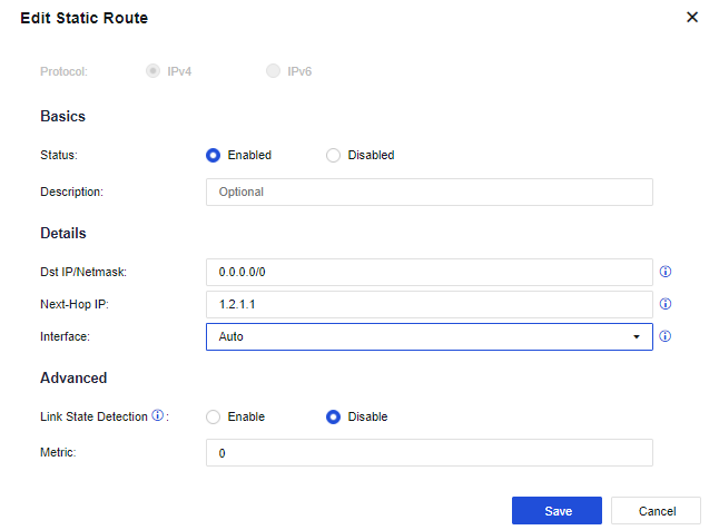
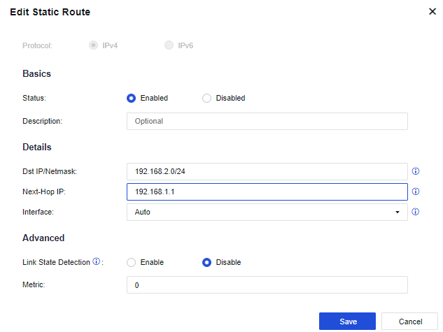
Step 3.Configure a route: You need to configure a default route to 0.0.0.0/0.0.0.0, pointing to the pre-gateway 1.2.1.2. Meanwhile, as the LAN interface is connected to multiple network segments spanning three layers. In this case, you need to configure another static route containing each network segment to the layer 3 switch. Go to the Network > Route > Static Route page and click Add to add a static route.
Configure the default routing Dst IP/Netmask as 0.0.0.0/0 and the Next-Hop IP as 1.2.1.1, and configure the backhaul routing (LAN segment routing) Dst IP/Netmask as 192.168.2.0/24 and the Next-Hop IP as 192.168.1.1. See the figure below.
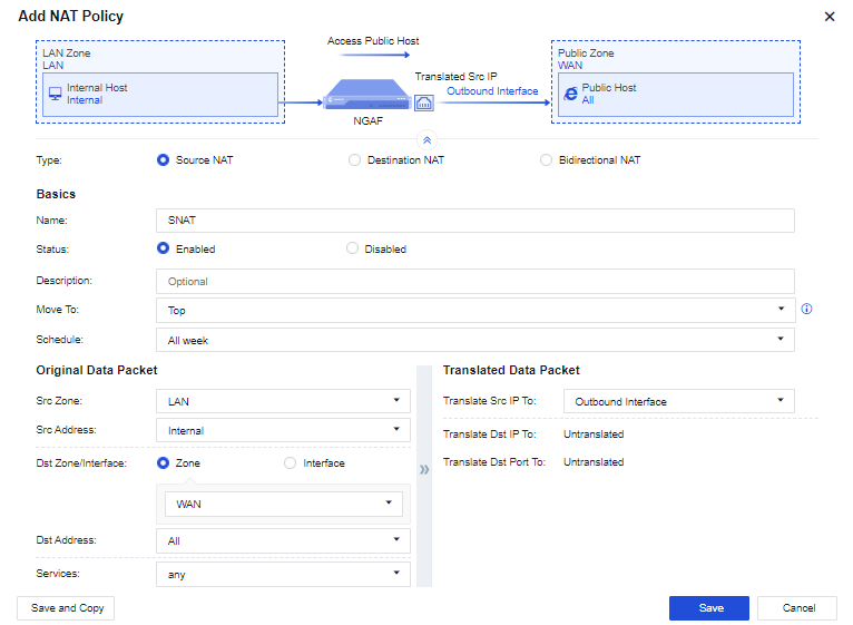
Step 4.Configure the proxy LAN: Go to Policies > NAT > IPv4 NAT. Click Add to configure the SNAT. Then, on the displayed page, select the custom LAN zone as the Src Zone, the custom LAN address as Src Address, the custom WAN zone as Dst Zone, All in Dst Address, any in Services, and Outbound Interface in Translate Src IP To respectively. See the figure below.
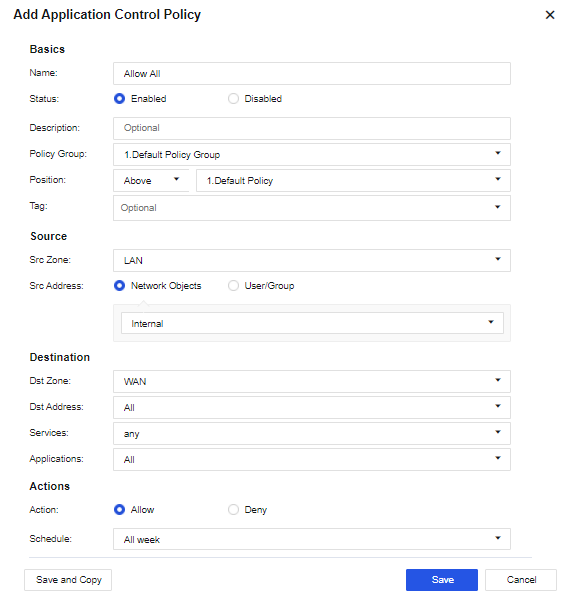
Step 5.Configure the application control policy: Assign the Internet access permissions to LAN users. Go to the Policy > Access Control > Application Control Policy page. Click Add. Assign the LAN-WAN data access permissions. Then, on the displayed page, select the custom LAN zone as the Src Zone, the custom LAN address as Src Address, the custom WAN zone as Dst Zone, All in Dst Address, any in Services, and All in Applications respectively. See the figure below.
Step 6.After completing the basic configuration, connect the device to the network, eth2 interface to the optical fiber, and eth3 interface to the layer 3 LAN switch.
1. When the device is working in the routing mode, the gateways of PCs on the LAN are directed to the IP address of the LAN interface or the layer 3 switch, with the gateway of the layer 3 switch directed to the device. Internet access data is subject to NAT by the device or is forwarded via the route by the device.
2. When the device has multiple routing interfaces, they can use the IP address of the same network segment. The static route will decide the networking interface from which data is to be forwarded.
3. The device supports routing interfaces configured with multiple WAN port attributes to connect to multiple external network lines, but authorization to open multiple lines is required.


 {{ $t('index.defaultHeader.chromeBrowserTip') }}