


{{ secondMenu.name }}




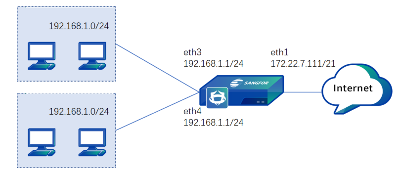
A company purchased Network Secure and deployed it at the company's outbound interface as a gateway. The R&D and business networks of the company access the internet through the outbound interface. The subnets of both networks are 192.168.1.0/24. The company requires two virtual firewalls on Network Secure to manage the networks separately, and the networks do not need to communicate with each other. It is also required that the business network can access all internet applications and that the R&D network can only access webpages. The following figure shows the topology.
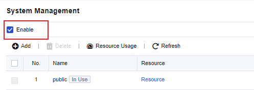
Step 1.Go to System > Virtual Systems > System Management. On the System Management page, check Enable.
Step 2.Click Add. In the Add Virtual System dialog box, set the name to "yanfa" (i.e.R&D), and select resources and a physical interface eth3 for the virtual system. You can use the default resource pool Resource or assign another resource pool as required.
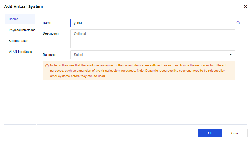
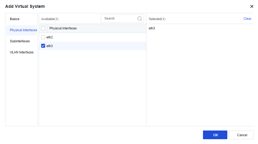
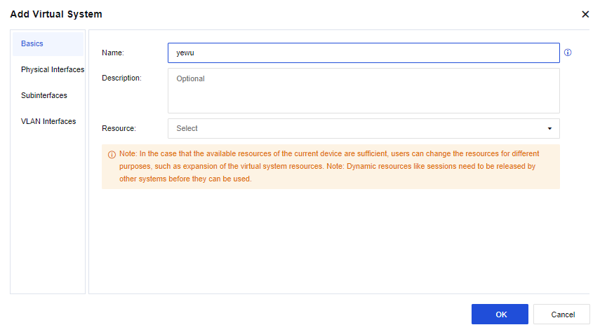
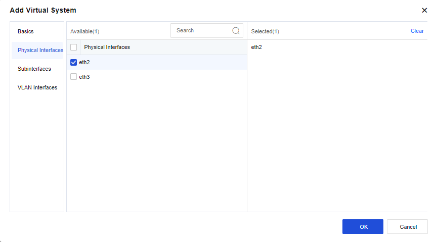
Step 3.Click Add. In the Add Virtual System dialog box, set the name to "yewu" (i.e. business) and select resources and a physical interface eth2 for the virtual system. You can use the default resource pool Resource or assign another resource pool as required.
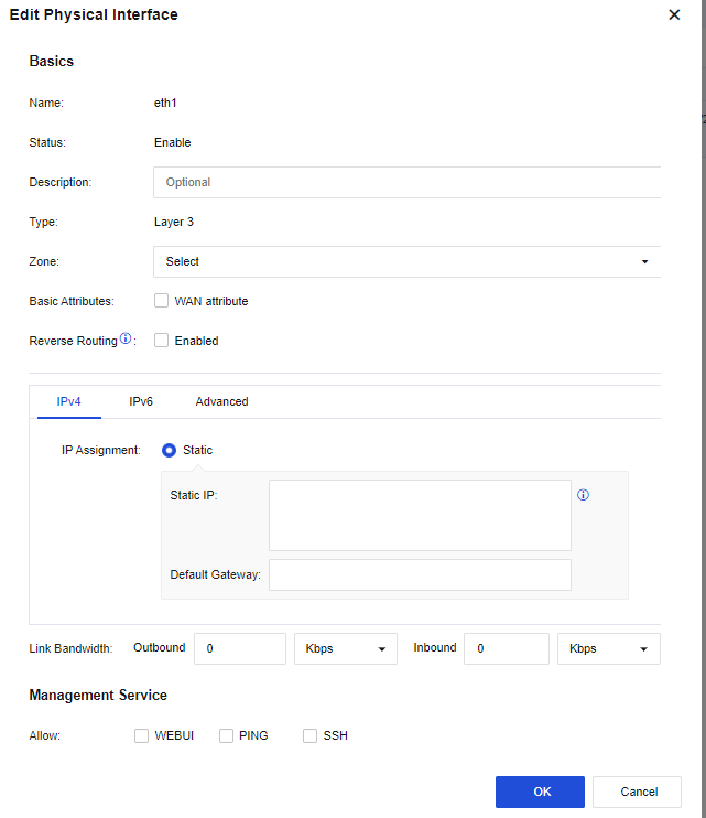
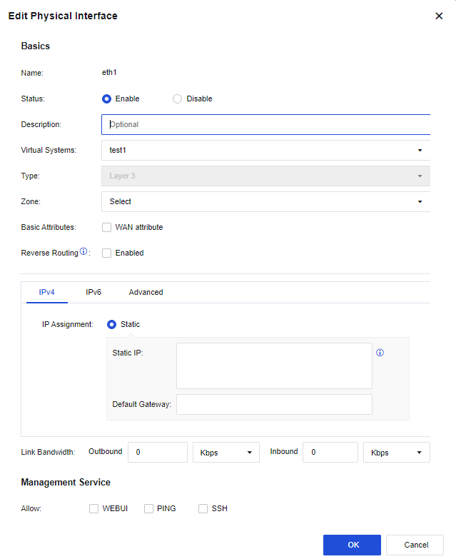
Step 4.Switch to the yanfa system and go to Network > Interfaces. On the Physical Interfaces tab, click Edit in the Operation column for physical interface eth1. In the Edit Physical Interface dialog box, select a zone and set the IP address to 192.168.1.1/24.
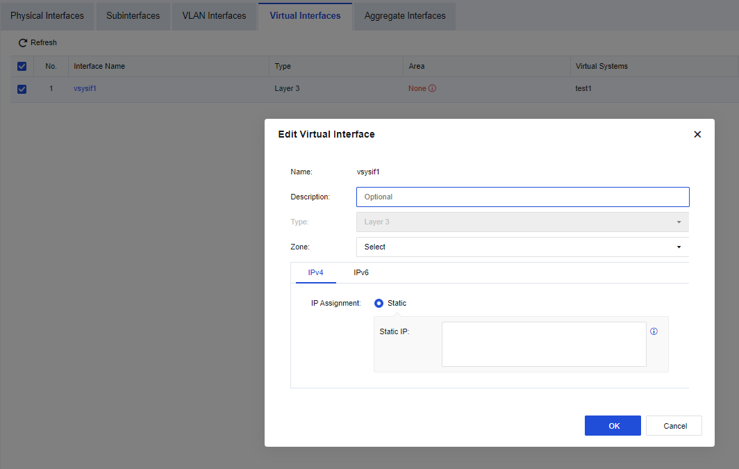
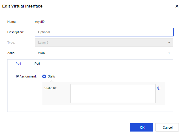
Step 5.In the yanfa system, go to Network > Interfaces. On the Virtual Interfaces tab, click Edit in the Operation column for virtual interface vsysif1. In the Edit Virtual Interface dialog box, select a zone and set the IP address to 172.16.1.1/24.
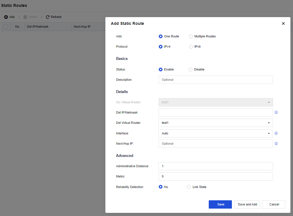
Step 6.In the yanfa system, go to Network > Routes > Static Routes. On the Static Routes page, configure a default route directing to the public system of the destination virtual router.
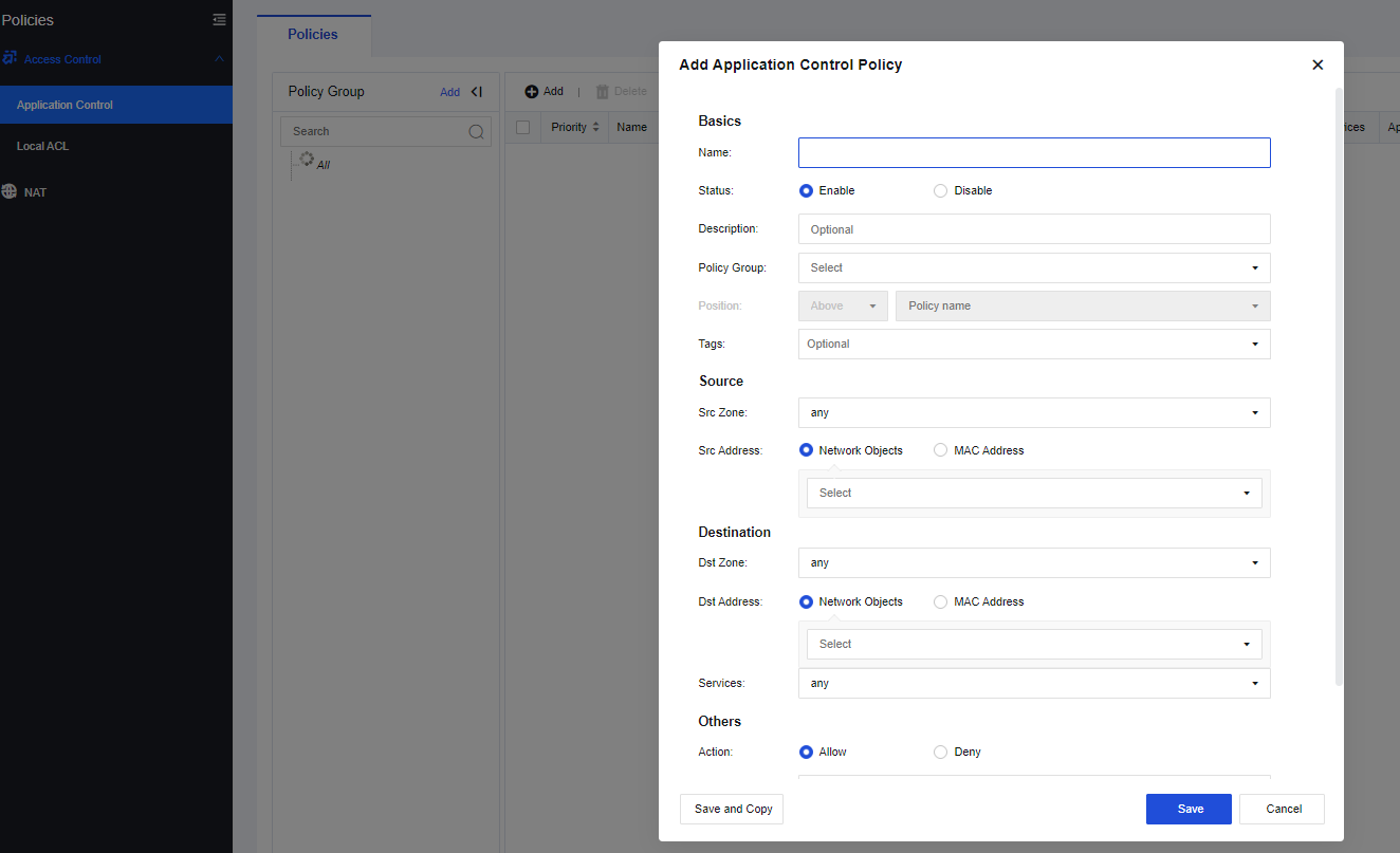
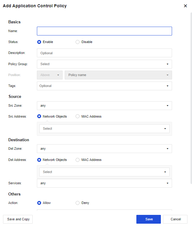
Step 7.In the yanfa system, go to Policies > Access Control > Application Control. On the Policies tab, add an application control policy to allow HTTP, HTTPS, and DNS services in the corresponding zone.
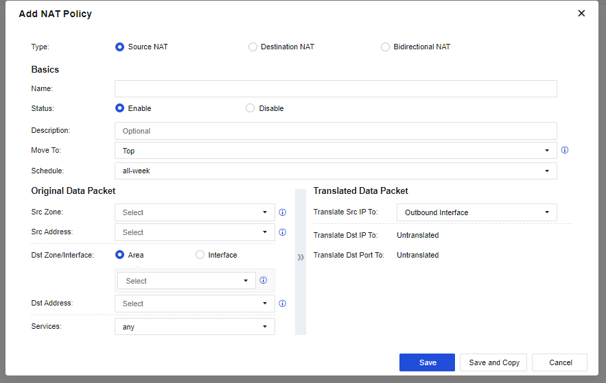
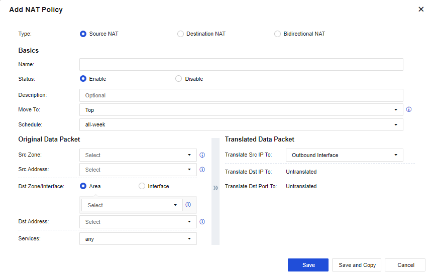
Step 8.In the yanfa system, go to Policies > NAT. On the IPv4 NAT tab, add a NAT policy to translate the source IP of the corresponding zone to the address of the outbound interface.
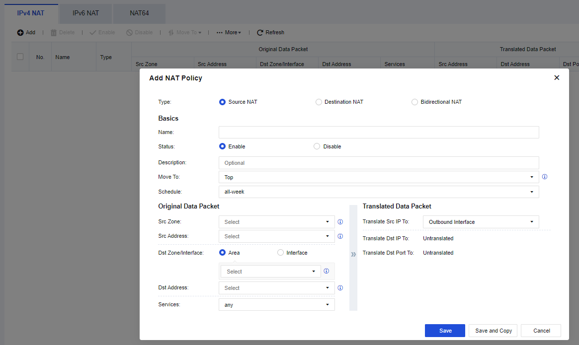
Step 9.Switch to the yewu system and go to Network > Interfaces. On the Physical Interfaces tab, click Edit in the Operation column for physical interface eth1. In the Edit Physical Interface dialog box, select a zone and set the IP address to 192.168.1.1/24.
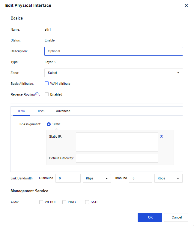
Step 10.In the yewu system, go to Network > Interfaces. On the Virtual Interfaces tab, click Edit in the Operation column for virtual interface vsysif2. In the Edit Virtual Interface dialog box, select a zone and set the IP address to 172.16.2.1/24.
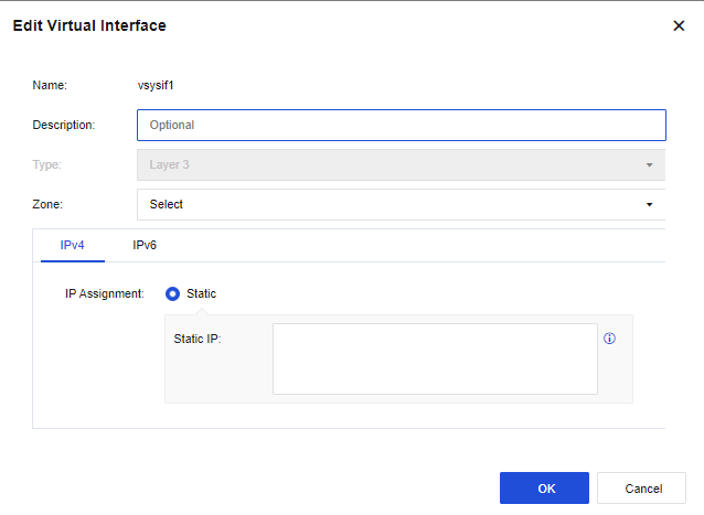
Step 11.In the yewu system, go to Network > Routes > Static Routes. On the Static Routes page, configure a default route directing to the public system of the destination virtual router.
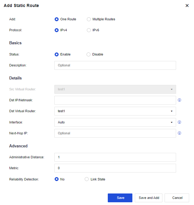
Step 12.In the yewu system, go to Policies > Access Control > Application Control. On the Policies tab, add an application control policy to allow all services in the corresponding zone.
Step 13.In the yewu system, go to Policies > NAT. On the IPv4 NAT tab, add a NAT policy to translate the source IP to the address of the outbound interface.
Step 14.Switch to the public system and go to Network > Interfaces. On the Physical Interfaces tab, click Edit in the Operation column for physical interface eth1. In the Edit Physical Interface dialog box, select a zone and set the IP address to 172.22.7.111/21.
Step 15.In the public system, go to Network > Interfaces. On the Virtual Interfaces tab, click Edit in the Operation column for virtual interface vsysif0. In the Edit Virtual Interface dialog box, select a zone and set the IP address to 172.16.3.1/24.
Step 16.In the public system, go to Network > Routes > Static Routes. On the Static Routes page, configure a default route directing to the next-hop outbound interface of the internet and static routes respectively directing to the yanfa and yewu systems, with the destination IP set to the addresses of interfaces vsys1 and vsys2.
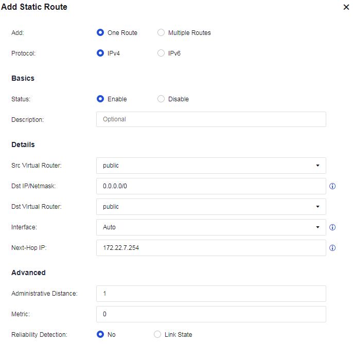
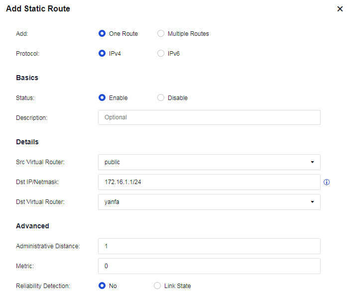
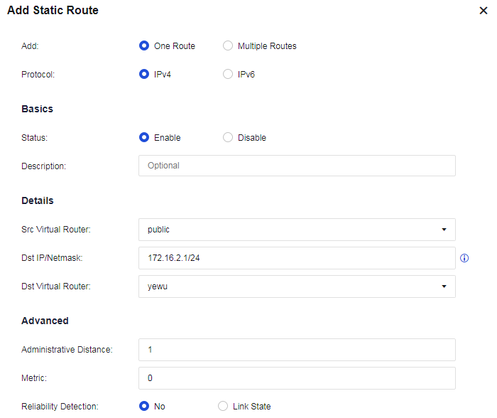
Step 17.In the public system, go to Policies > Access Control > Application Control. On the Policies tab, add an application control policy to allow all services in the corresponding zone.
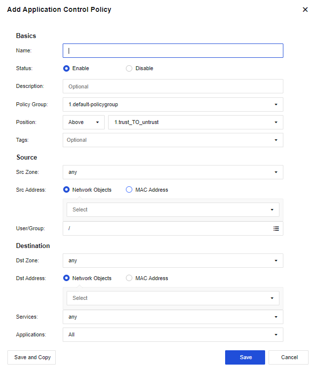
Step 18.In the public system, go to Policies > NAT. On the IPv4 NAT tab, add a NAT policy to translate the source IP to the address of the outbound interface.
Step 19.Verify network access on the R&D and business networks.


 {{ $t('index.defaultHeader.chromeBrowserTip') }}