


{{ secondMenu.name }}




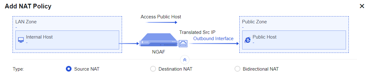
To translate the source IP address of data that meets translation conditions. In the most common scenarios, when the device is deployed at the internet egress and acts as a proxy for LAN users to access the internet, you must add a SNAT policy to translate the source IP address. On the IPv4 NAT tab, you can manage, add, or delete an SNAT policy. The SNAT process is shown in the following figure.
If an enterprise needs to enable both LAN users and server groups to access the internet through Network Secure, you must add a SNAT policy on the Network Secure device. In this way, when data that is generated by accessing the internet through the network segments192.168.1.0/24 and 172.16.1.0/24 passes through Network Secure, its IP address can be translated into 1.2.1.1, the IP address of the Network Secure device's egress interface ETH1.
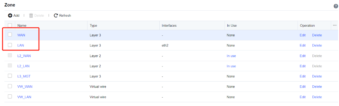
Step 1.Define LAN and WAN zones. Before you add an SNAT policy, navigate to Network > Zones and select the zone to which the interface belongs on the Zones page. Then, navigate to Objects > Network Objects and select the IP address group to which the LAN segment belongs. In this example, select WAN for the ETH1 interface and LAN for the ETH2 interface, and define the network segments 172.16.1.0/24 and 192.168.1.0/24 as Internal on the Network Objects tab.

Step 2.Add a NAT policy. Navigate to Policies > NAT > IPv4 NAT and click Add. Then, the Add IPv4 NAT dialog box appears. By default, Source NAT is selected. In the Basics section, enter the name of the policy in the Name field, enter a custom description in the Description field, and specify the Position and Schedule parameters.
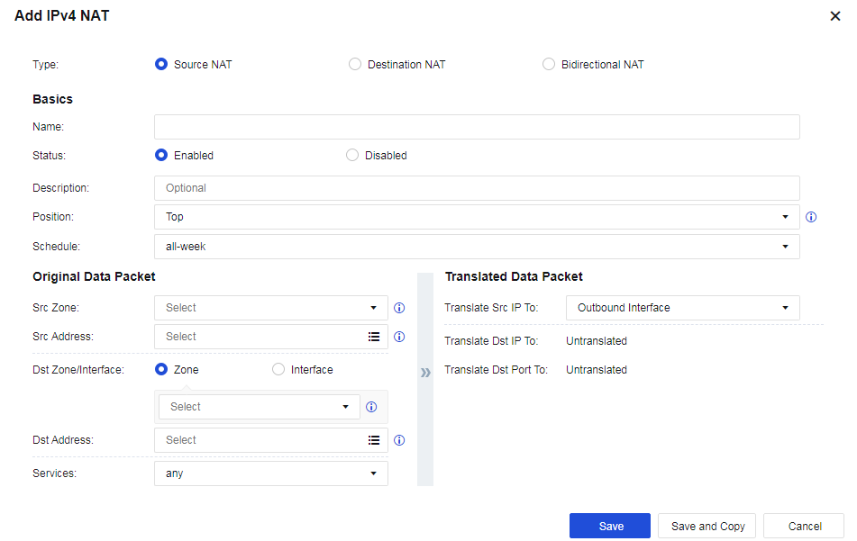
Step 3.Set an Original Data Packet to comply with the policy.
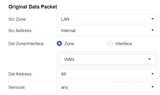
• Src Zone and Src Address: Select the source IP address for which an SNAT policy is added. This is because only data from the specified source zone and specified source IP address can match this policy to enable SNAT. If the routing interface acts as a proxy for LAN users to access the internet, you can set the Src Zone parameter to LAN and the Src Address parameter to Internal or All. In this example, select LAN for the Src Zone parameter and Internal for the Src Address parameter.
• Dst Zone/Interface and Dst Address: Set destination data that complies with the policy, such as data to the specified destination zone, accessing the specified destination IP address group, and outgoing from the specified interface. If the routing interface acts as a proxy for LAN users to access the internet, you can set the Dst Zone/Interface parameter to WAN and the Dst Address parameter to All. In this example, select WAN for the Dst Zone/Interface parameter and All for the Dst Address parameter.
• Services: Set this parameter if SNAT is set only for the data conforming to the specified protocol, source port, and destination port. To set this parameter, click the drop-down list. In this example, you do not need to set this parameter, and any is selected by default.
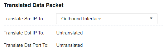
Step 4.Set a Translated Data Packet. If you select Source NAT for Type, set a specified IP address to which the source IP address of data conforming to the specified source IP address, destination IP address, and service is translated. You can select Outbound Interface, IP Range, IP Address, Network Object, or Untranslated for the Translate Src IP To parameter. In this example, select Outbound Interface from the drop-down list.
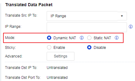
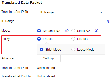
• Mode: You can set the Mode parameter to Dynamic NAT or Static NAT after selecting an IP range.
• Sticky: You can configure the sticky mode after selecting an IP range or network object. The sticky NAT escape feature ensures traffic continuity in case of port request failure through sticky NAT by requesting ports from the configured IP addresses. When entering the escape mode, an alert log will be generated to notify you that the current network environment has entered the sticky NAT escape mode. Two escape modes, Strict Mode and Loose Mode, are supported. When in Strict Mode, packets with the same source IP address are assigned the same IP address because the source IP addresses of the packets serve as the keys for IP address querying from the IP range or IP object. However, in the event of port resource request failure, an error log is printed, and the "droplist" process starts. When in Loose Mode, in the event of port resource request failure through sticky NAT, Network Secure moves forward from the failed IP address (a.b.c.d) to the next IP address within the configured IP range for requesting a port. If the port request succeeds, the resource is returned; if the port request fails, Network Secure proceeds to the next IP address to request a port until the last IP address in the configured IP range is reached. If no port is available after Network Secure proceeds to the last IP address, Network Secure moves backward from the failed IP address (a.b.c.d) to the previous IP address for requesting a port. If the port request succeeds, the resource is returned; if the port request fails, Network Secure proceeds to the previous IP address to request a port until the first IP address in the configured IP range is reached. If no port is available from all IP addresses in the IP range, an error log is printed, and the "droplist" process starts.
• Advanced: You can configure advanced settings after selecting an IP Range, IP Address, or Network Object.
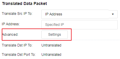
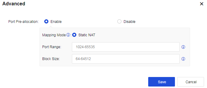
You can click Settings to enable or disable Port Pre-allocation, as shown in the following figure.
Step 5.Save the configuration. Finally, click Save. Then, the configuration of the SNAT policy is complete.

Step 6.After the application control strategy from the LAN to the WAN is allowed, use a PC in the LAN segment to normally access the WAN.


 {{ $t('index.defaultHeader.chromeBrowserTip') }}