


{{ secondMenu.name }}




Mix deployment refers to the Layer 3 interfaces, Layer 2 interfaces, and virtual wire interfaces that exist simultaneously on the Network Secure device. You can select the deployment mode depending on different customer demands.
Deployment Case of Mix Mode
An enterprise's LAN has many server clusters for users to access through the Internet, with the IP address(es) of the Internet assigned to each server. This enterprise wants to deploy the Network Secure device on the Internet port so that users can directly access server clusters through the Internet IP address and does not want to publish the server through port mapping. Also, it hopes the Network Secure device serves as a LAN proxy to access the Internet. The network topology is shown in the following figure.
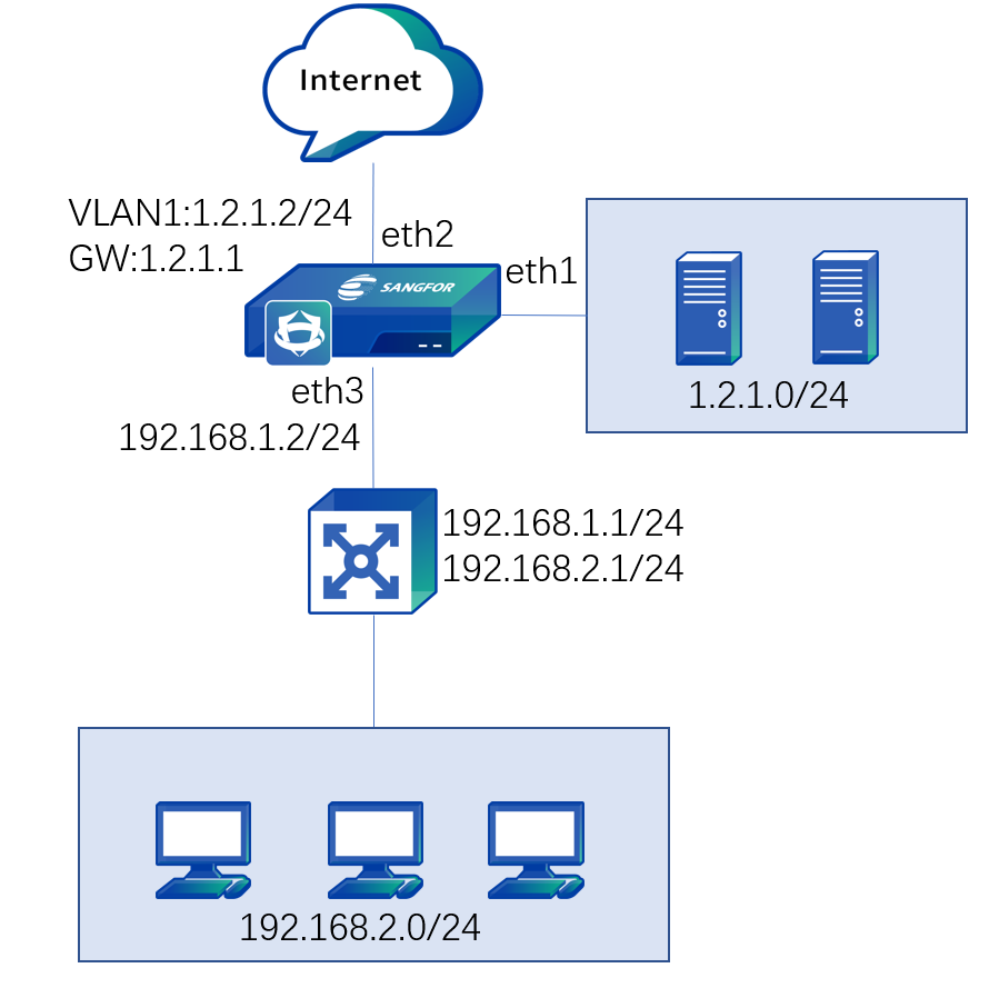
In this case, the users need to access the server through the server's Internet IP address. It is required to set the Network Secure device's eht2 interface connected to the Internet and the eth1 interface connected to the server cluster on the LAN as the transparent access interface, belonging to the same VLAN. Set a VLAN interface and configure an Internet address for it. Set the eth3 interface connected to the LAN as the routing interface. When LAN users access the Internet, they can convert the source IP address to the Internet IP address of the VLAN interface. By doing so, the users' demand is met.
Step 1.Log in to the device through the default IP address of the management interface (ETH0). The default IP address of the management interface is 10.251.251.251/24. You need to configure an IP address in the same network segment on the computer and log in to the device via https://10.251.251.251.
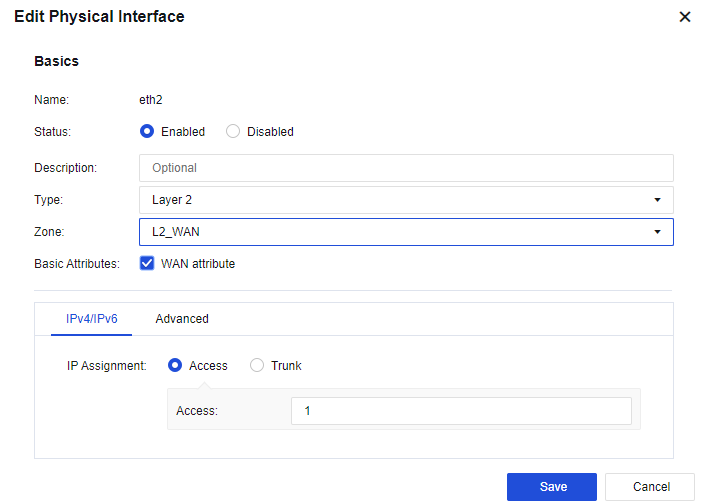
Step 2.Set the WAN interface. On the Network > Interfaces > Physical Interface page, select eth2 as the WAN interface. Click eth2, select the Layer 2 type, select the custom WAN in Zone, check the WAN attribute option, and set IP Assignment to Access 1, as shown below.
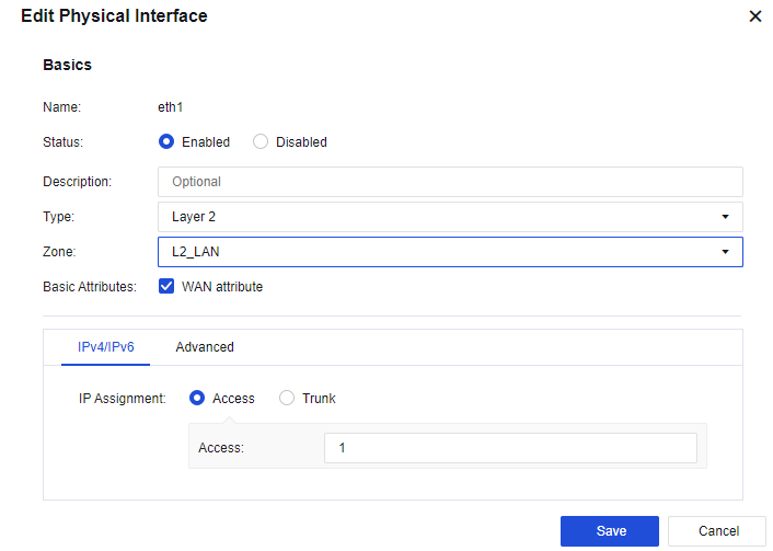
Step 3.Set the server zone interface. On the Network > Interfaces > Physical Interface page, select eth1 as the server zone interface. Click eth1, select the Layer 2 for Type, select the custom WAN in Zone, and set IP Assignment to Access 1, as shown below.
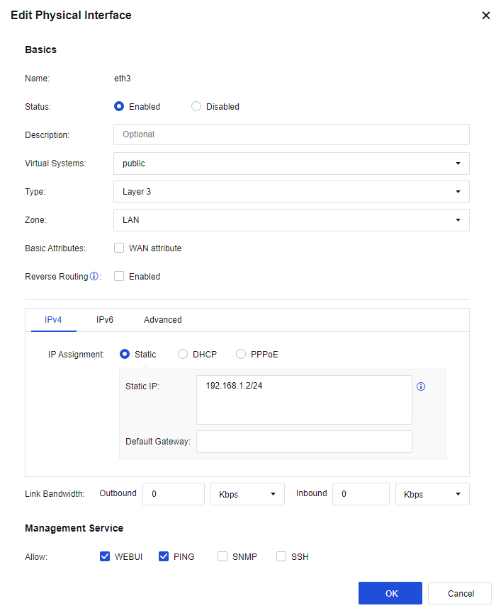
Step 4.Set the LAN interface. On the Network > Interfaces > Physical Interface page, select eth1 as the server zone interface. Click eth3, select the Layer 3 type, select the custom LAN in Zone, and enter the IP address 192.168.1.2/24, as shown below.
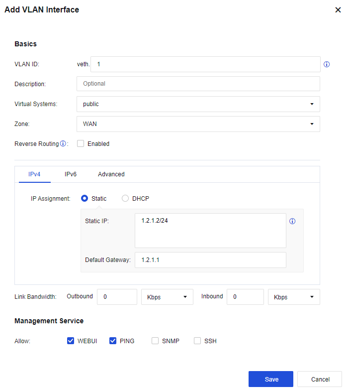
Step 5.Set the VLAN interface. On the Network > Interfaces > VLAN Interfaces page, click Add, set the VLAN ID field to 1, select the custom WAN in Zone, enter the IP address 1.2.1.2/24, and configure the next-hop gateway to 1.2.1.1, as shown below.
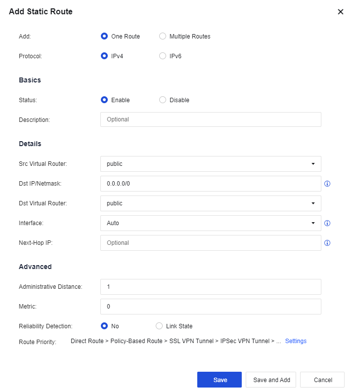
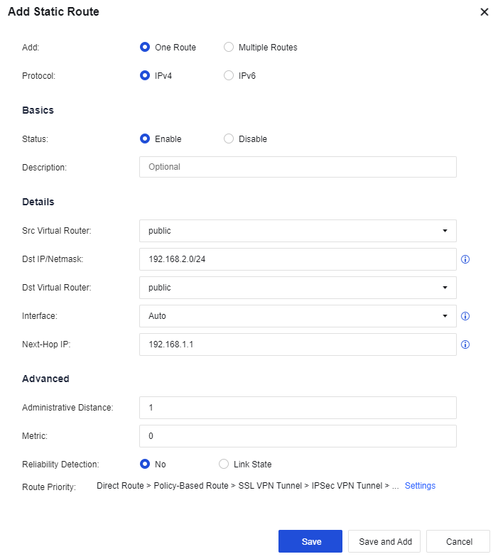
Step 6.Configure routing. You need to configure a default route to 0.0.0.0/0.0.0.0, pointing to the next hop 1.2.1.2. Meanwhile, as the LAN interface is connected to multiple network segments spanning three layers in this case, you need to configure a static route containing each network segment to the layer 3 switch. Go to the Network > Route > Static Route page and click Add to add a static route. Specifically, configure the default routing Dst IP/Netmask as 0.0.0.0/0 and the Next-Hop IP as 1.2.1.1, and configure the backhaul routing Dst IP/Netmask as 192.168.2.0/24 and the Next-Hop IP as 192.168.1.1. See the figure below.
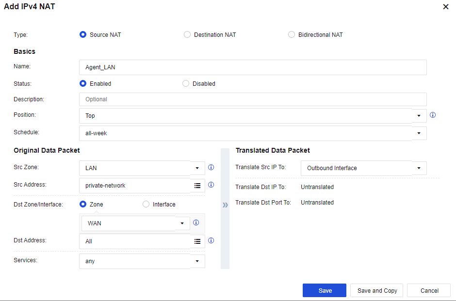
Step 7.Configure the NAT policy. Go to Policies > NAT > IPv4 NAT. Click Add to configure the SNAT. Then, on the displayed page, select the custom LAN zone as the Src Zone, the custom LAN address as Src Address, the custom WAN zone as Dst Zone, All in Dst Address, any in Services, and Outbound Interface in Translate Src IP To respectively. See the figure below.
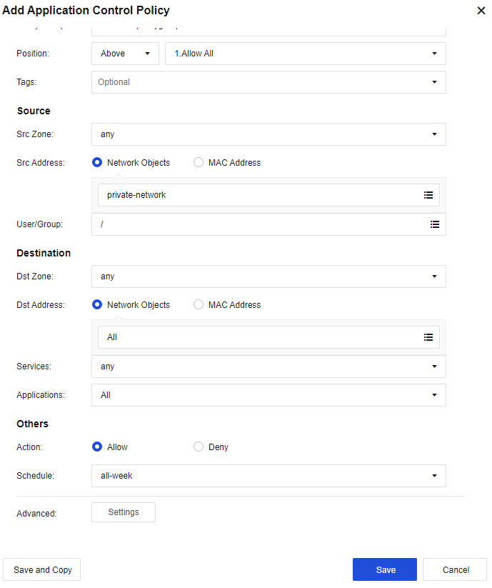
Step 8.Configure the application control policy. Assign the Internet access permissions to LAN users. Go to the Policies > Access Control > Application Control Policy page. Click Add. Assign the LAN-WAN data access permissions. Then, on the displayed page, select the custom LAN zone as the Src Zone, the custom LAN address as Src Address, the WAN zone as Dst Zone, All in Dst Address, any in Services, and All in Applications. See the figure below.
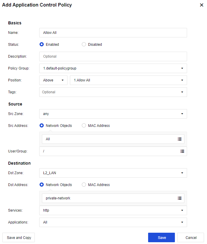
Step 9.Configure the application control policy. Allow all zones to access servers. Select any in the Src Zone, All in the Src Address, the server zone in the Dst Zone, and the custom server in the Dst Address. Services can be configured based on actual needs, such as HTTP. See the figure below.
Step 10.After the above steps, connect the device's eth2 interface to the WAN line, eth1 interface to the server zone, and eth3 interface to the LAN switch.


 {{ $t('index.defaultHeader.chromeBrowserTip') }}