{{ secondMenu.name }}


Description
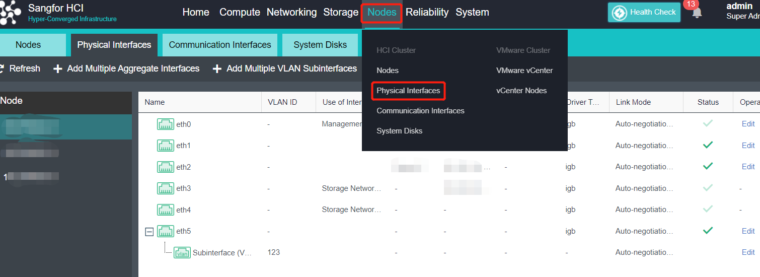
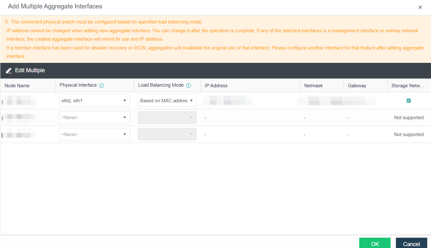
When the physical NIC of the server is insufficient, the four networks multiplexing can be adopted. The four network multiplexing is a network planning scheme in which the management network, physical edge network, overlay network, and storage network interface reuse one aggregation interface. The scheme provides NIC-level redundancy protection, and the failure of a single NIC will not affect the service.
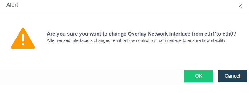
Precautions
Prerequisites
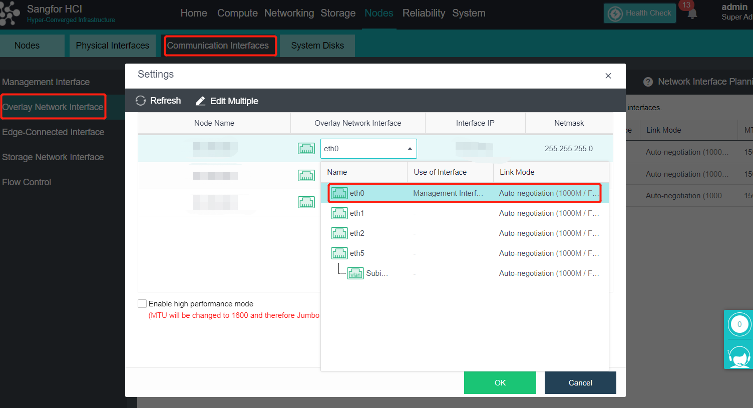
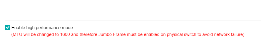
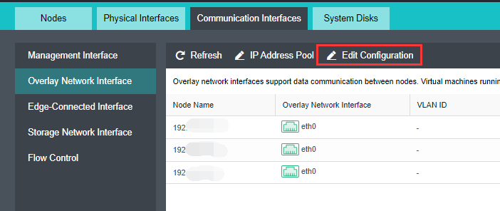
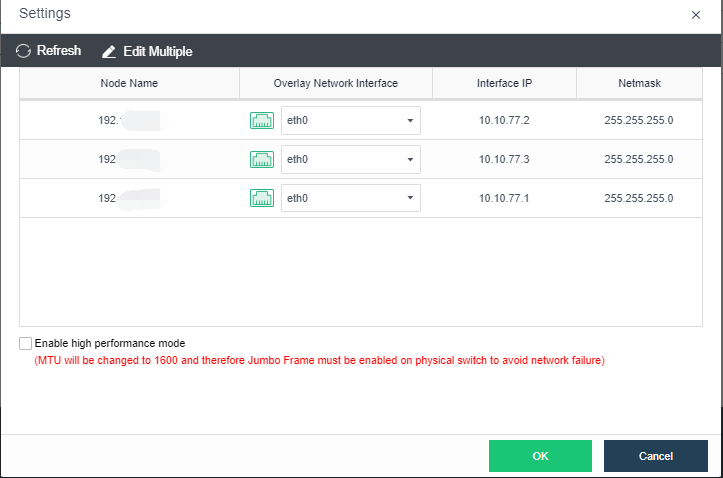
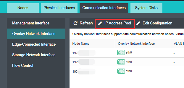
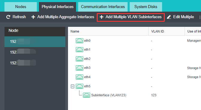
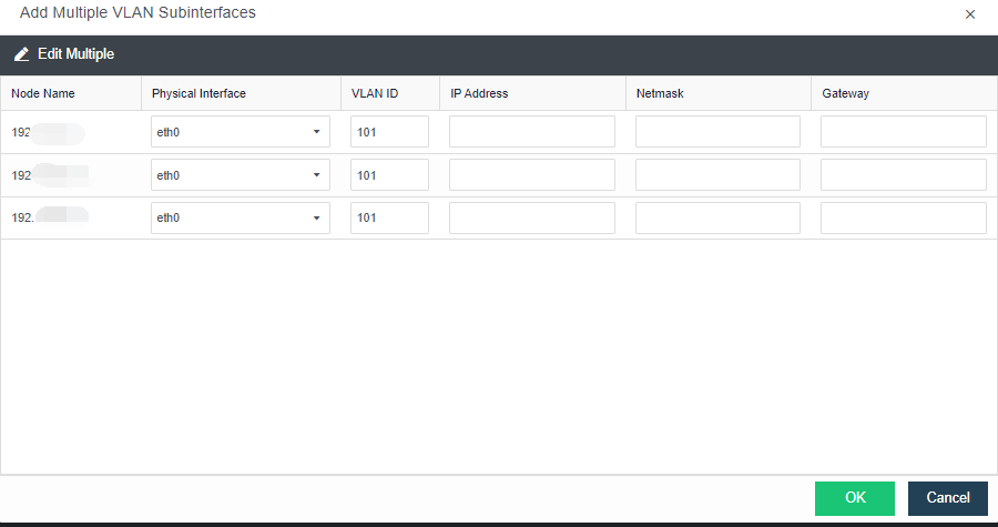
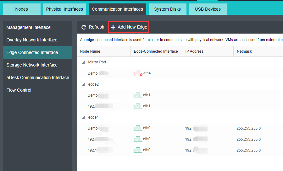
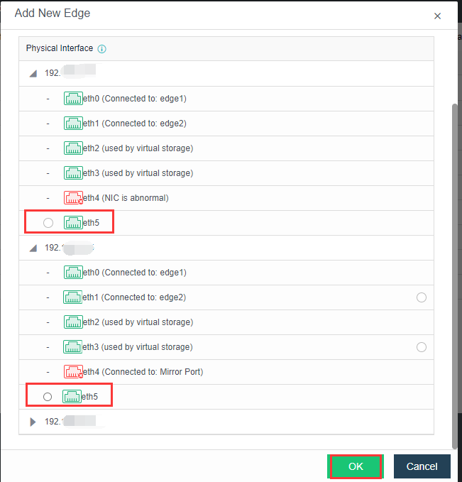
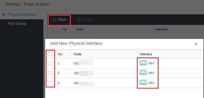
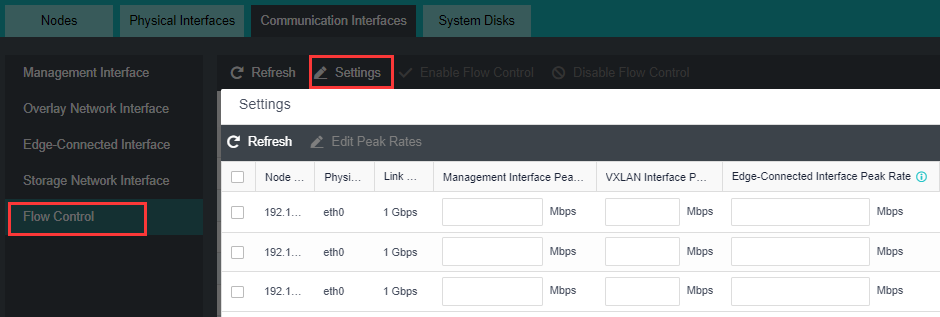
Steps


 {{ $t('index.defaultHeader.chromeBrowserTip') }}