{{ secondMenu.name }}


Precautions
Steps
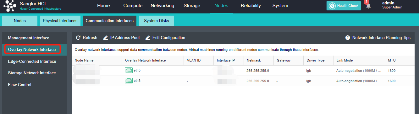
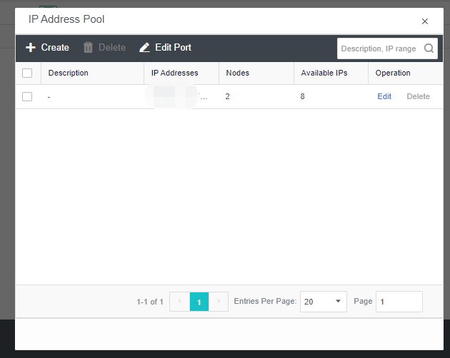
• Create: a VXLAN IP pool can be created. Multiple VXLAN IP pools can exist in a cluster. A node is only allowed to join one VXLAN IP pool.
• Delete: You can delete the VXLAN IP pools that are no longer in use.
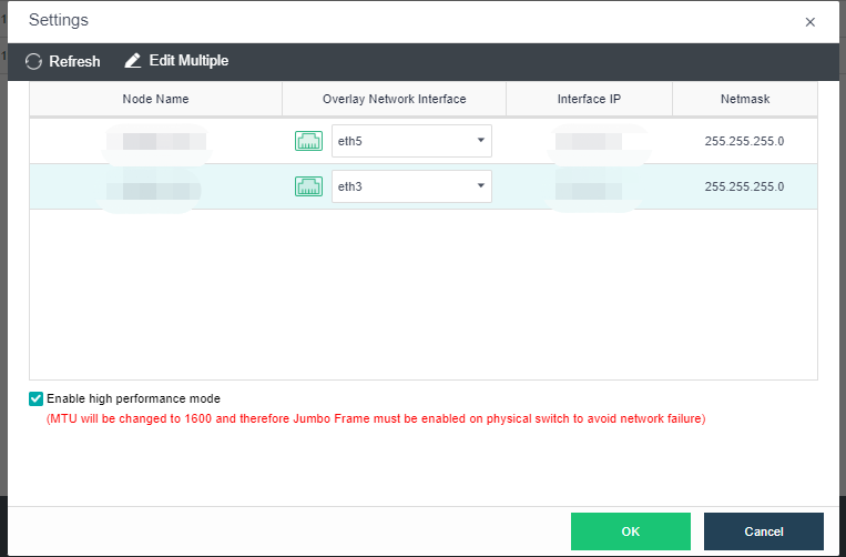
• Edit Port: The port number used for VXLAN can be modified. The port number supports 8472, 4789 and 4790.
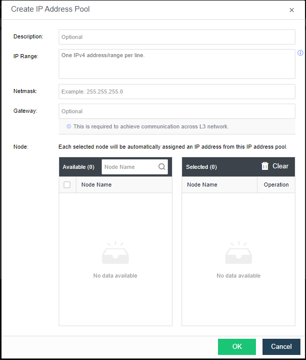
• Description: Describes the created VXLAN IP pool information.
• IP Range: The IP address used by the VXLAN node network plane. It supports a single IP setting and range setting and can be set in multiple lines. It is necessary to ensure that all addresses are in the same network segment.
• Netmask: The mask information of the IP address in the VXLAN IP pool.
• Gateway: If cross-layer data communication is required, fill in the layer 3 gateway.
• Node: The node that uses the IP in the VXLAN IP pool.

 {{ $t('index.defaultHeader.chromeBrowserTip') }}