


{{ secondMenu.name }}




config system virtual-wan-link
set status enable # enable SD-WAN feature
config members
edit 1
set interface "wan1" # physical interface name for link 1
set gateway 100.64.1.1 # next-hop gateway IP for wan1
set cost 10 # link cost metric (lower = preferred)
set weight 60 # load-balancing weight percent
next
edit 2
set interface "wan2" # physical interface name for link 2
set gateway 100.64.2.1
set cost 20
set weight 40
next
end
config health-check
edit "Internet_Monitor"
set server "8.8.8.8" # probe target (public DNS)
set protocol ping # probe method: ping/http/tcp
set interval 5 # probe interval (seconds)
set failtime 5 # consecutive failures to mark down
next
end
config service
edit 1
set name "Internet_Browsing" # service rule name
set dst "all" # destination match (all destinations)
set mode load-balance # mode: load-balance or priority
set priority-members 1 2 # ordered member preference
next
end
end
| Fortigate Parameter |
Description |
Corresponding Module / Parameter in Sangfor NGAF |
Migration Recommendation |
| config members |
Defines SD-WAN participating link members |
Network > Routes > Policy-Based Routes |
Add each WAN interface in NGAF and specify its gateway |
| set interface "wan1" |
Local physical/logical interface used by this member |
Network > Routes > Policy-Based Routes |
Ensure interface mapping is consistent and label interface purpose clearly |
| set gateway 100.64.1.1 |
Next-hop gateway for the member |
Network > Routes > Policy-Based Routes |
Configure the gateway in the NGAF outbound interface settings |
| set cost 10 |
Link cost used for priority (lower value = higher priority) |
Network > Routes > Policy-Based Routes |
Map the cost value to PBR/outbound priority (lower comes first) |
| set weight 60 |
Load-balance weight |
Network > Routes > Policy-Based Routes |
Configure weighted traffic distribution in PBR (e.g., WAN1:60% / WAN2:40%) |
| config health-check |
Defines link health-check |
Network > Routes > Policy-Based Routes |
Add link-health detection in NGAF with the same probe target and interval |
| set server "8.8.8.8" |
Probe target (IP/URL) |
Network > Routes > Policy-Based Routes |
Use the same stable public IP as the probe target |
| set protocol ping |
Probe protocol (ping/http/tcp) |
Network > Routes > Policy-Based Routes |
NGAF supports ARP, PING, and BFD |
| set interval 5 / set failtime 5 |
Probe interval and failure threshold |
Network > Routes > Policy-Based Routes |
Align interval and failure threshold to ensure consistent behavior |
| config service / set dst "all" |
Specifies the traffic type applied to the policy |
Network > Routes > Policy-Based Routes |
Create a PBR rule in NGAF: match "any" → select outbound interface |
| set mode load-balance |
Load mode (load-balance/priority) |
Network > Routes > Policy-Based Routes |
If using load-balance on Fortigate, enable weighted load-balancing in NGAF PBR |
| set priority-members 1 2 |
Priority order of members |
Network > Routes > Policy-Based Routes |
Configure preferred and backup outbound interfaces in PBR |
Policy-Based Routes
The operation objects of policy-based routing are data packets. Suppose a routing table has been generated; instead of performing forwarding according to the routing table, the method of its forwarding path is changed according to a certain policy as needed. The primary function is to select the outbound interfaces and lines, according to the source/destination IP addresses, source/destination ports, protocols, and other conditions, when the device has multiple WAN interfaces connecting with multiple WAN lines.
The link fault detection function shall be enabled for the interface/zone. See the figure below.

Source-Based Route
When multiple lines connect to the internet, define the matching conditions according to the source/destination IP addresses, ports, protocols, and applications. Select and specify the line's outbound interface or next-hop IP address for traffic matched with conditions, such as a multi-ISP routing scenario. Click Add and select Source-Based Route, as shown in the figure below.
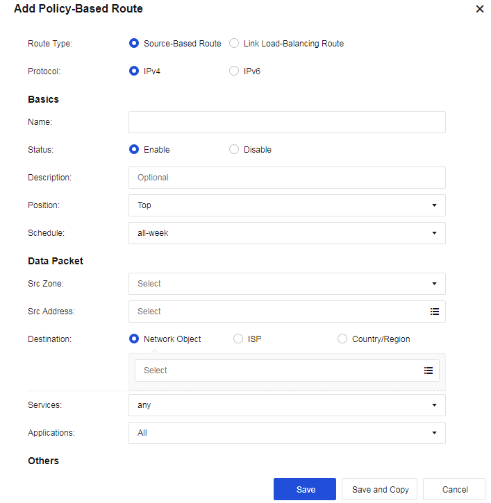
Route Type: You can select Source-Based Route or Link Load-Balancing Route.
Protocol: You can select IPv4 or IPv6.
Name: Fill in the corresponding name.
Description: Fill in the description of the route.
Schedule: Specify the effective time range of the policy.
Move To: Put the policy before X, and the matching order is from top to bottom.
Data Packet: Filter and select the corresponding data packet information for matching.
Src Zone: The source zone for matching.
Src Address: The source network object for matching, which is then filtered source IP address.
Destination: The destination address for matching. Network Object, ISP, and Country/Region are optional for calling.
• Network Object: Call network objects configured according to the actual situation.
• ISP: Perform routing according to ISPs. China Telecom, China Unicom, CERNET, and China Mobile are currently supported.
• Country/Region: Perform selection by country/region.
Services: The service objects that need to be matched, as shown in the figure below. 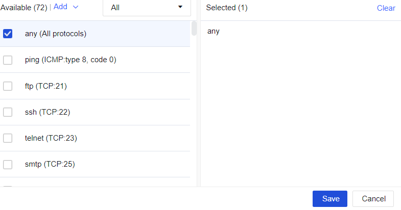
Applications: The applications that need to be matched, as shown in the figure below. 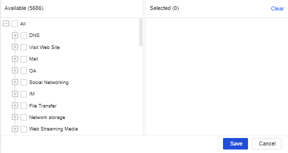

Applications are hidden by default. Go to System > General Settings > Network and check the Allow associating policy-based routes with applications checkbox.
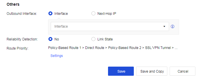
Interface and Next-Hop IP: Set the next-hop IP address and outbound interface for the next-hop direction of traffic sent to the destination IP address.
Reliability Detection: You can select No or Link State.
Route Priority: Specify the device's route priorities. You can click Settings to change the priority.
Configuration Case
A user wants to access an online bank with the address 100.100.100.100 using the HTTPS access protocol. The online bank will verify the IP address used for accessing. The online bank will deny access if the source IP address in the same connection is changed. In this case, set a policy-based route and specify that the data accessing the destination IP address is permanently sent out through the line connected to the eth1 interface.
Step 1.On the Navigation Menu page, choose Network > Routes > Policy-Based Route, click Add, select Source-based route for Route Type, and select IPV4 for Protocol. Fill in the fields under Basics and Data Packet, as shown below.

Step 2.Configure the outbound interface: eth1, as shown in the following figure. 
Step 1.Click Save to complete the configuration, as shown in the following figure. 
Link Load-Balancing
When a company has multiple lines connecting to the internet, define the matching conditions according to source/destination IP addresses, ports, protocols, and applications, and select policies for the outbound interface to perform dynamic routing to realize effective bandwidth utilization and load balance for these lines.
Click Add and select Link load-balancing, as shown in the figure below. 
Outbound Interfaces: Select multiple outbound interfaces for the policy and then perform load balancing according to the policy. Click Add to add outbound interfaces, as shown in the figure below. 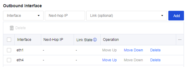
Link State: The line will be regarded as faulty when configuring link detection for an interface, and either PING or DNS detection fails.
Load Balancing Method: Perform traffic load balancing according to the algorithm. There are four algorithms:
• Round robin: Evenly allocate connections to multiple WAN lines.
• Bandwidth ratio round robin: Allocate connections according to the ratio of WAN lines bandwidth.
• Weighted least traffic: Compare the current line traffic to the line bandwidth and select the line with the minimum ratio to prioritize connecting first.
• Prefer link at top: It is used in scenarios requiring active and standby lines. All connections are allocated to the first line. If the first line fails, the connection will be switched to the second selected available line.
Configuration Case
A user has 2 WAN lines: China Telecom 2M and 10M lines. The user wants to realize that when LAN users access public networks, the line with the least traffic is automatically selected.
Step 1.Navigate to Network > Routes > Policy-Based Route, and click Add to add link load-balancing routes. The page is as follows. 
Step 2.Configure interfaces, as shown in the following figure. 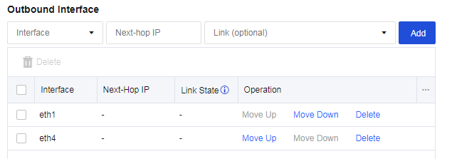
Step 3.Select the Load Balancing Method, as shown in the following figure.

Step 4.Configure Link State Detection for the corresponding interface. Ensure the link switching can be performed when a link fails, as shown in the following figure. 
Step 5.Check the configuration, as shown in the following figure. 
1. To implement load-balancing among multiple WAN lines, Link State Detection must be enabled.
2. For link load-balancing, only WAN attribute interfaces can be selected.
3. Each WAN line must have a corresponding policy-based route, which can be a source-based route or a link load-balancing one.


 {{ $t('index.defaultHeader.chromeBrowserTip') }}