{{ secondMenu.name }}


On the Troubleshooting page, you can query which module of the device rejects a packet and the rejection reasons to quickly locate a configuration error or test whether some rules take effect. Click Settings. On the Filter page, set all kinds of filtering conditions, as shown in the following figure.
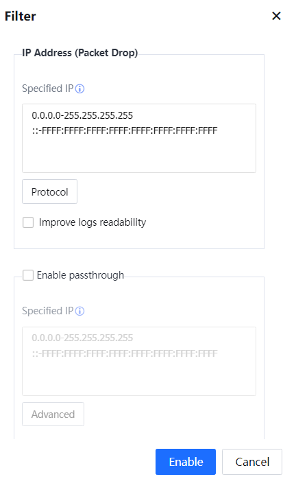
Specified IP: Specifies an IP address enabling the rejection list. By default, the rejection list applies to all network segments. Click Protocol and set the protocol type and port range for filtering interception logs, as shown in the following figure.
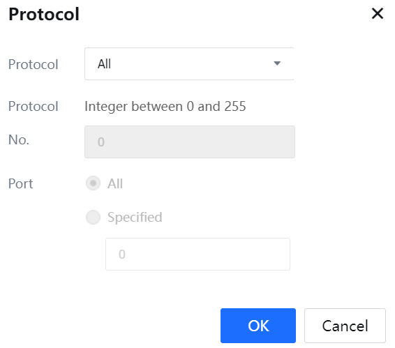
Protocol Type can be set to All, TCP, UDP, ICMP, or Others.
Select Improve Logs Readability to display interception logs in Chinese. If this option is not selected, interception logs are displayed in English.
Select Enable Pass-Through and set an IP address or IP address segment. The Internet access policies are ineffective for the specified IP addresses. Packets that should be rejected according to Internet access policies will be allowed to pass.
Click Advanced and set whether to enable pass-through transmission for the traffic control module, as shown in the following figure.
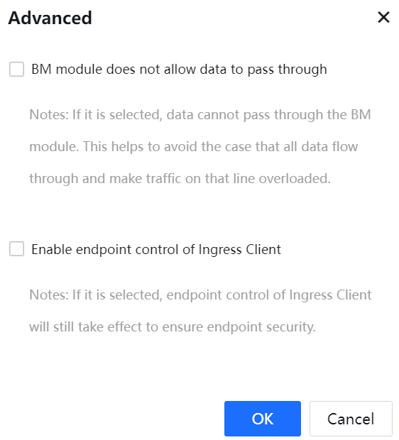
If BM module does not allow data pass-through is selected, the Bandwidth Management policies are still effective. It protects the network environment against excessively heavy traffic because all data are transmitted straight through. If this option is not selected, the Bandwidth Management policies are ineffective. By default, pass-through transmission is not enabled for the Bandwidth Management module.
Click Enable to enable the interception logging and pass-through transmission functions.
Status shows the enabling status of the pass-through transmission and interception logging functions, as shown in the following figure.
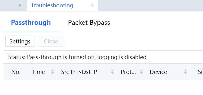
Click Close to disable the interception logging and pass-through transmission functions.
Click Refresh to view interception logs, and the packet interception conditions, as shown in the following figure.
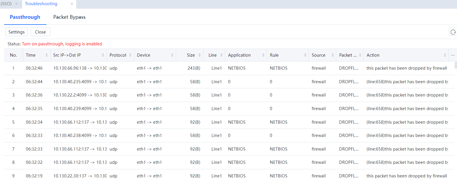
![]()
After the interception logging and pass-through transmission functions are enabled, if the administrator does not manually click Close, these functions are still enabled even if the device is restarted.
Packet Bypass:
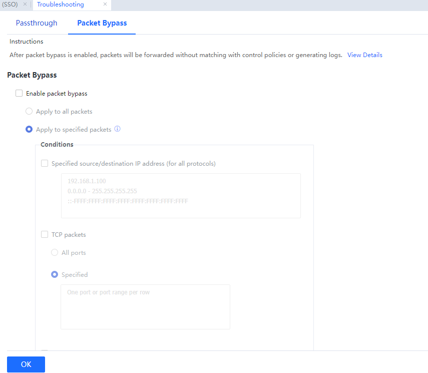
Instructions:
Packet bypass uses a traffic passthrough mechanism to bypass packets if the IAG device fails to function properly due to an error, ensuring business continuity. Different from the Passthrough and Global Exclusion, packet bypass forwards packets, which will not match with control policies, and has no logs generated. Additionally, this function can dramatically reduce the usage of resources usages such as CPU, memory, and I/O.
![]()
1. After packet bypass is enabled, the Internet access traffic will be forwarded without being controlled by the policies, such as user authentication, access control, bandwidth control, and Internet access audit policies.
2. This function does not apply to some packets, such as broadcast and multicast packets.
3. The connections established before this function is enabled will not enter packet bypass status.
4. The connections established before this function is disabled will not exit packet bypass status until they are destroyed.
5. If a control connection enters packet bypass status, so does its data connection, and vice versa.
6. After packet bypass is enabled, the Ingress Client may fail to connect automatically to IAG devices and obtain ingress policies, the anti-DoS attack feature may encounter an error and cannot reach the virtual IP address under bridge mode, etc.

 {{ $t('index.defaultHeader.chromeBrowserTip') }}