{{ secondMenu.name }}


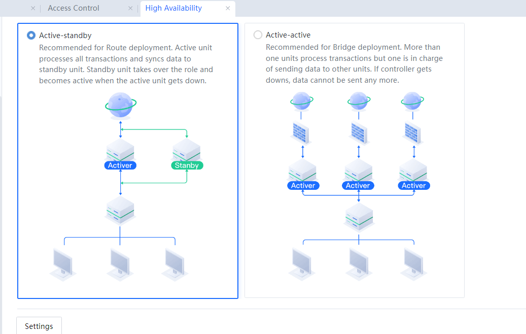
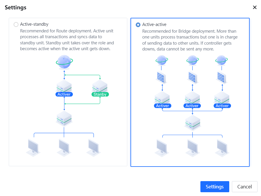
There are two high availability (HA) modes: Active-Standby and Active-Active. In Active-Standby mode, two devices interwork with each other over a communications interface for mutual backup. This mode applies when there are two lines in Active-Standby mode. The two devices connect to the active and standby lines. When the active line fails, the standby line and standby device become active. The configurations on the standby device are the same as those on the active device.
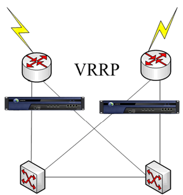
In Active-Active mode, multiple devices interwork over the communications interface for synchronizing configurations and user status information. The devices work at the same time. In this way, when a line fails, the device can seamlessly switch to another line, ensuring policy and user status consistency. It is similar to the working principle in a VRRP environment. Both modes aim to ensure network stability. However, they differ in the number of working devices. In Active-Active mode, multiple devices work at the same time. In Active-Standby mode, the two devices work in mutual backup mode, and only one device is online. Choose an HA mode depending on the actual environment.
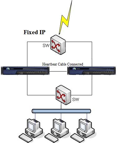
In Active-Standby mode, two devices interwork with each other over an HA interface for mutual backup. This mode applies when there are two lines in Active-Standby mode. The two devices connect to the active and standby lines. When the active line fails, the standby line and standby device become active. The configurations on the standby device are the same as those on the active device. The following figure shows the topology.
Active-standby deployment in route mode:
The procedure is as follows:
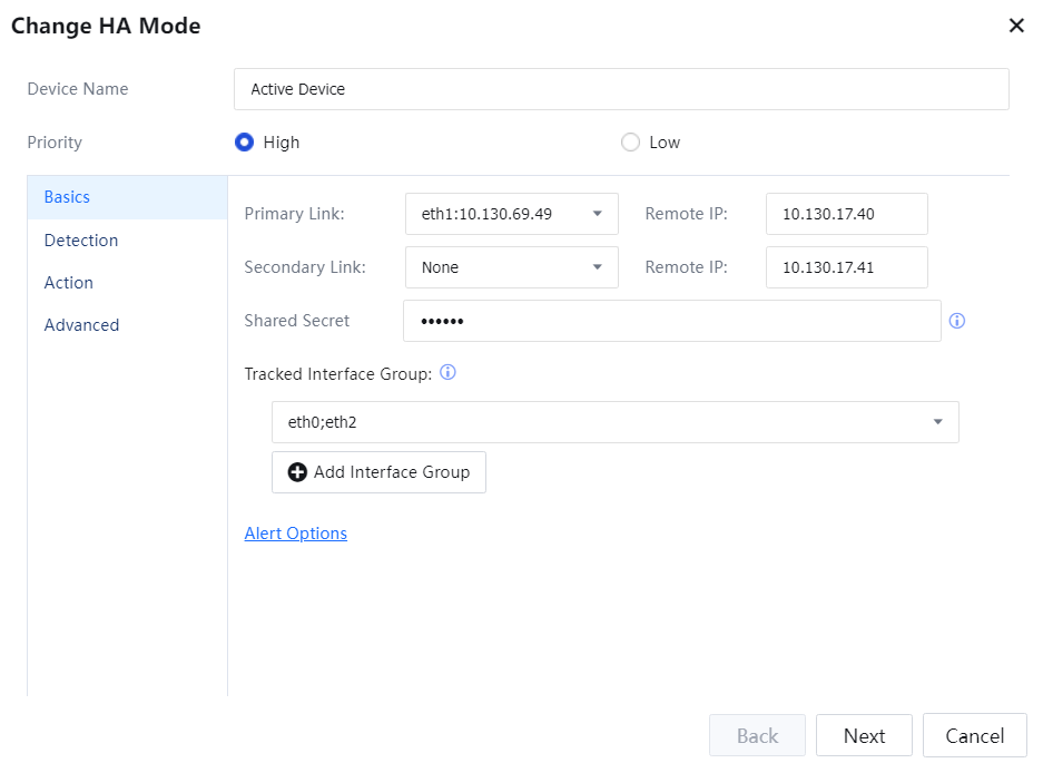
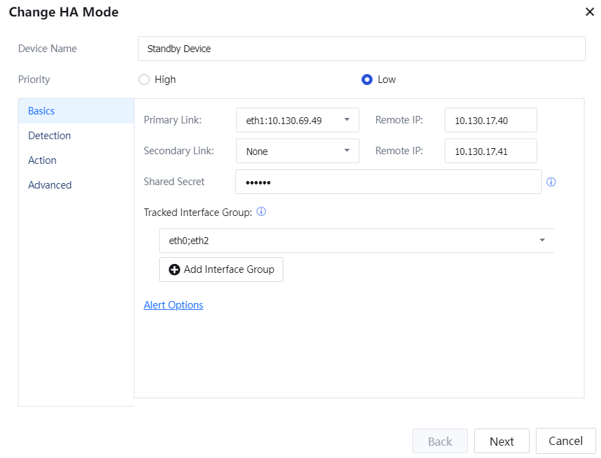
Device Name: Enter a name to distinguish the current device from the other.
Priority: Set the priority of two devices. The recommended host priority is high, and the standby priority is low.
Primary Link: in the active-standby mode, you can set two sets of HA ports, the Primary Link and the Secondary Link. The Primary Link is a required option. The Secondary Link is a fillable option. In addition, the network configuration of the Primary Link and Secondary Link are not synchronized. In active-standby mode, you can use the network port of the DMZ port or another unconfigured area.
Shared Secret: Configure a key the active device uses to connect to the standby device. This key must be the same as that configured for the standby device.
Tracked Interfaces Groups: Configure the interfaces groups to be tracked. The interface that is not used by the device does not need to be selected. In addition, the interfaces in the interfaces group are in the status of mutual backup. When all the interfaces in the same interface group are offline simultaneously, the interface group enters the fault status.
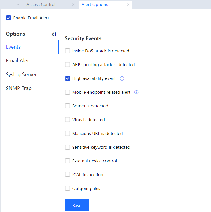
Alert options: Click alert options. You can jump to the email alarm events settings page and select the High Availability event, as shown in the following figure.
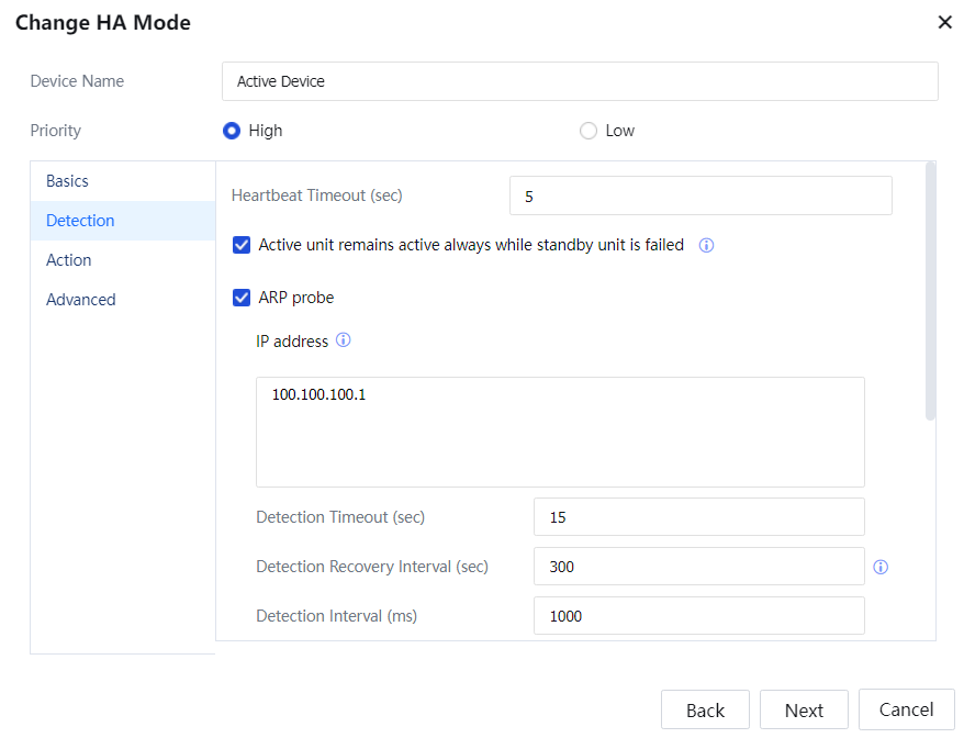
Heartbeat Timeout: Active-standby heartbeat timeout setting.
Active unit remains active always while standby unit is failed: Including ARP detection and ICMP detection. When the standby device is already in the fault status, and the current device only has ARP detection failure or ICMP detection failure, the host status is still working normally.
ARP detection detects the address of the device's uplink or downlink device. If any one of the detections fails, the ARP detect fails. In addition, the ARP detection can set the detection timeout, the detection recovery interval, and the detection interval.
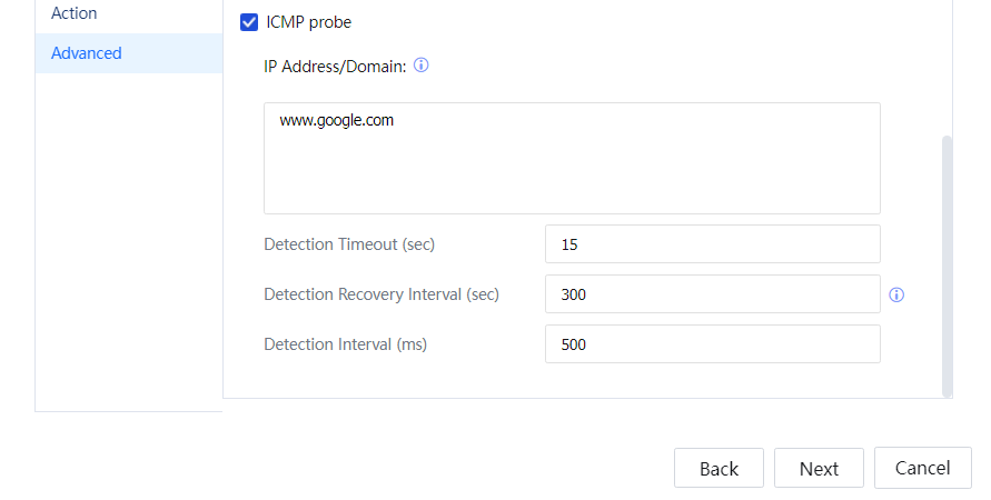
ICMP detection mainly detects the connectivity of the filled host IP or domain name. The probe IP/domain name can support multiple entries. Only when all IP or domain name detection fails the ICMP detection fails The ICMP detection can set the detection timeout, the detection recovery interval, and the detection interval.
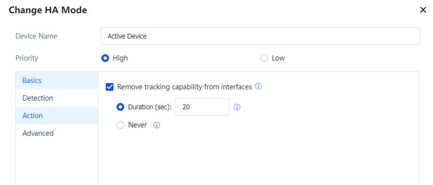
Remove tracking capability from interfaces: This feature is not selected by default. When the device enters standby, all interfaces in the monitoring interfaces group are disabled. The device is used to notify the device to switch between uplink and downlink devices.
Click OK[A248], and the configuration of the active device is complete.
After Low has been selected on the priority of the standby device. The configuration method is the same as the active device. Please note that the standby device's priority is different from the active device. The primary link of the standby device needs to write the address of the active device. The Detection and Action refer to the active device configuration.
The Active-Active mode applies to the VRRP-enabled intranet. Devices on the intranet work in hot backup and load sharing modes. The deployment of the devices will not affect the operation and switchover of the original network. As shown in the following figure, configure multiple Sangfor IAGs in Active-Active mode. Ensure that the device can work properly after a VRRP switchover due to a link fault. In addition, ensure that the device configuration and user status are consistent with those on the other device. The following figure shows a typical application scenario.
The active-active mode requires no physical interface if a node device can route to the control device.
The configuration procedure is as follows:
After Low has been selected on the priority of the standby device. The configuration method is the same as the active device. Please note that the standby device's priority is different from the active device. The primary link of the standby device needs to write the address of the active device. The Detection and Action refer to the active device configuration.
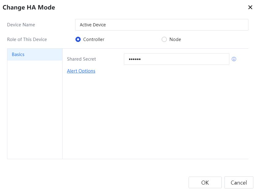
Device Name: Enter a name for distinguishing the current device from the other.
Role of This Device: Select Controller or Node. If the Controller is selected, you only need to configure a shared key. If Node is selected, you need to configure the control device's IP address and shared key. We select Controller here.
Shared Secret: Configure a key the control device uses to connect to a node device. This key must be the same as that configured for the node device.
Alert options: Click Alert options, and you will be redirected to the email alarm events page and select the High Availability event, as shown in the following figure.
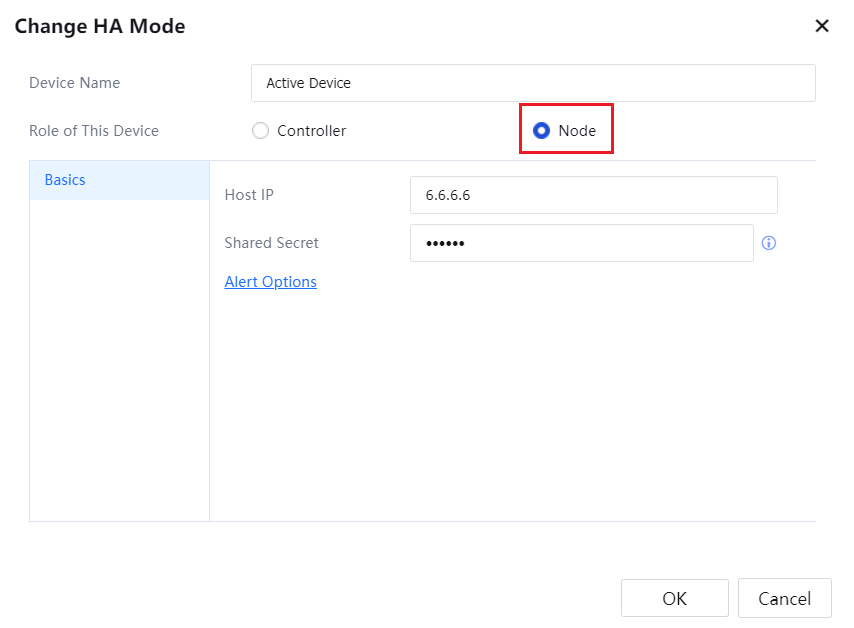
Host IP: Enter the IP address of the control device.
Shared Secret: Configure a key the control device uses to connect to a node device. This key must be the same as that configured for the control device.
After configuration, the page showing the information about the online device is displayed.
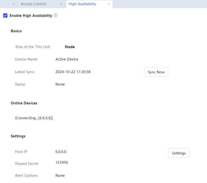
The Controller can synchronize the configuration, click Sync Now, and the device will send a synchronization signal. Perform device configuration and information synchronization—Online Node showing all online nodes.
The configurations on the node device cannot be modified and can only be synchronized from the control device.
![]()
The precautions for configuring an HA mode are as follows:
1. In Active-Standby mode, the two devices need to be connected using a heartbeat cable instead of a serial cable. Therefore, the deployment mode needs to be adjusted. A direct upgrade is not supported by default.
2. In Active-Standby mode, if the HA interface of the standby device is connected, the connection will fail. During connection, an error message indicating the failure reasons will be displayed.
3. In Active-Standby mode, a DMZ interface or a network interface that does not belong to any zone can be used. The network configuration of the HA interface will not be synchronized. If a DMZ interface is configured as the HA interface, the network configuration of the DMZ interface will not be synchronized either.
4. In Active-Active mode, the status of online users is synchronized in real time. In other words, if a new user is authenticated, the user status will be immediately synchronized. However, the online status of users (only the IP address and MAC address are bound) that do not require authentication will not be synchronized.
5. The Active-Active mode is exclusive to an Ingress policy or the security desktop. If an Ingress policy or security desktop policy is configured, the Active-Active mode cannot be enabled.
6. In Active-Active mode, no physical interface is required if a node device can route to the control device.
7. After a device is added to an Active-Active or Active-Standby group. It does not need to restart.
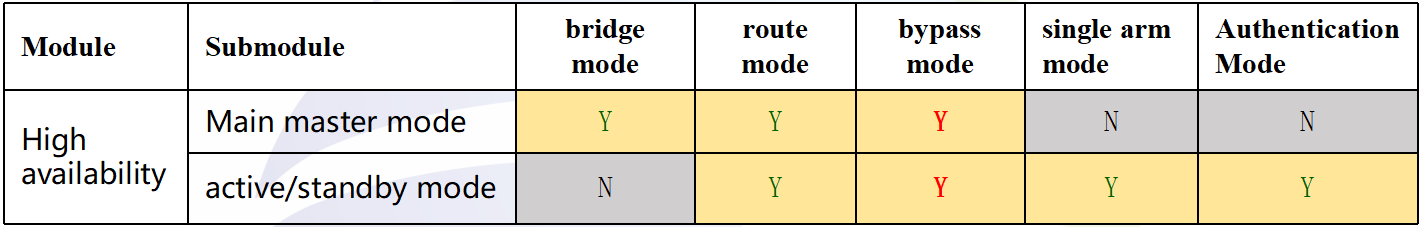
8. A device supports only Active-Active in bridge mode and Active-Active and Active-Standby in route mode. If Active-Standby is used in bridge mode, an upgrade cannot be performed, and a message will be displayed, prompting the customer to change the HA mode to Active-Active.
High availability support in various modes is as follows:
SPs can be synchronized by default, but those with a special mark cannot. For KBs and custom devices, synchronization is supported if the installed patch packages are the same (insensitive to the sequence). New configurations of custom devices also support synchronization.
If the R versions are inconsistent, synchronization is not supported. The description of the HA indicators status is as follows:
|
|
Active-Standby |
Active-Active |
||
|
|
Active Device |
Standby Device |
Control Device |
Node Device |
| Disconnected |
Off |
Off |
Off |
Off |
| Connected |
Steady green |
Blinking at 1 Hz |
Steady green |
Blinking at 1 Hz |
Table 8:HA comparison table
If the active or control device is disconnected, the HA indicator will always be on (indicating abnormal status).

 {{ $t('index.defaultHeader.chromeBrowserTip') }}