{{ secondMenu.name }}


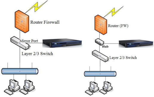
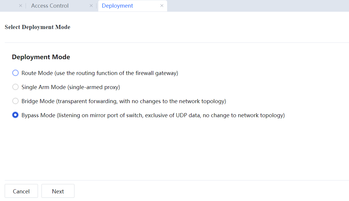
The device monitors, and controls function in bypass mode without modifying the original network structure or causing network interruption. The device is connected to the mirrored port of the switch or to a hub to ensure that Internet access data of intranet users passes through this switch or hub. Both outbound and inbound data are mirrored, thereby implementing monitoring and control of Internet access data. The bypass mode will not interrupt the network even if the device breaks down. Typical applicable scenarios are shown in the figures below.
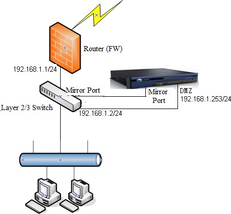
Example: The network topology is shown in the following figure. The device is to be deployed in bypass mode. The customer requires that Internet access data of all network segments on the intranet is under monitoring, that the device automatically updates the embedded rule library, and web authentication is performed for intranet users. The device console can be logged in from the intranet anytime for management.
Based on the customer requirements and network topology, deploy the device in bypass mode to communicate with both the external network and the intranet. However, the device cannot access networks over a mirrored port. To solve this problem, connect the device's management interface (DMZ interface) to the intranet switch and assign an idle IP address for the device to communicate with the public network and intranet. Then, connect the DMZ to the intranet switch.
The procedure is as follows:
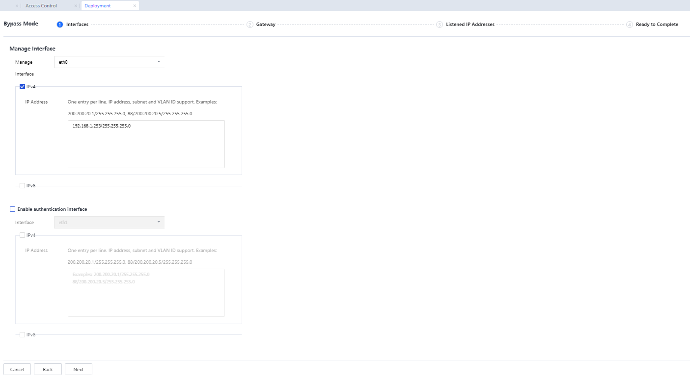
IP Address: Enter the IP address assigned to the management device (DMZ interface). In this example, the DMZ interface needs to be connected to the intranet switch. Therefore, enter an IP address for communication with the switch and intranet.
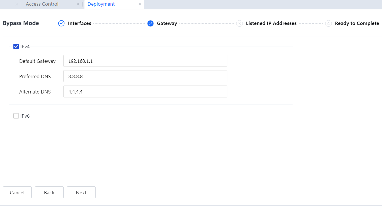
Default Gateway: Enter the IP address of the switch's network interface connected to the DMZ interface. Enter idle public network IP addresses in Preferred DNS and Backup DNS.
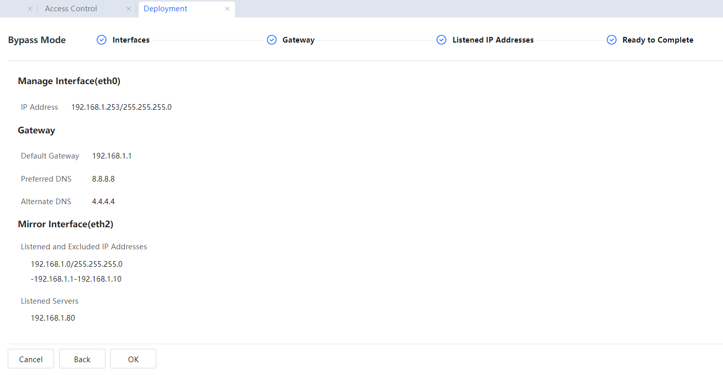
In Listened IP Address, enter the network segments to be monitored and the IP addresses to be excluded from monitoring. Enter the network segment 192.168.1.0/255.255.255.0 here. The access data from this network segment to other network segments will be monitored, and access data within this network segment will not be monitored. An excluded network segment should be entered in the correct format. For example, if you enter -192.168.1.1-192.168.1.10 when IP addresses within 192.168.1.1-192.168.1.10 access other network segments (external network), the data will not be monitored.
In Advanced, set the monitoring server list. If an IP address on a monitored network segment is accessed, the data will be monitored. For example, a web server exists on the intranet, and the customer needs to record the data when intranet users access this web server. Data will not be monitored for access within a network segment. Therefore, add the IP address of this webserver to the monitoring server list.
Some TCP control functions can be implemented in bypass mode based on the monitoring. In other words, only data that can be monitored can be controlled.

Restart the device for the configurations to take effect. In the displayed dialog box asking for your confirmation, click Yes.
![]()
1. The bypass mode applies when a hub or the switch acts as a mirrored port. If the switch does not have a mirrored port, a hub can be deployed before the switch.
2. In bypass mode, the traffic and active connection rankings are displayed as invalid.
3. In bypass mode, TCP control is achieved by sending reset packets through the DMZ interface. Therefore, ensure that PCs and public network servers can receive the reset packets sent through the DMZ interface.
4. Many functions, such as VPN and DHCP, cannot be implemented in bypass mode.
5. In bypass mode, the device mainly implements the monitoring function, and the control function is not as comprehensive as in route mode and bridge mode. Only TCP connections can be restricted, such as URL filtering, keyword filtering, and mail filtering. User Datagram Protocol (UDP) connections, such as P2P connections, are not restricted.
6. In bypass mode, the traffic diagrams are displayed when the mirrored interface is a WAN interface. When a WAN interface is connected, there is only received traffic and no transmitted traffic.

 {{ $t('index.defaultHeader.chromeBrowserTip') }}