{{ secondMenu.name }}


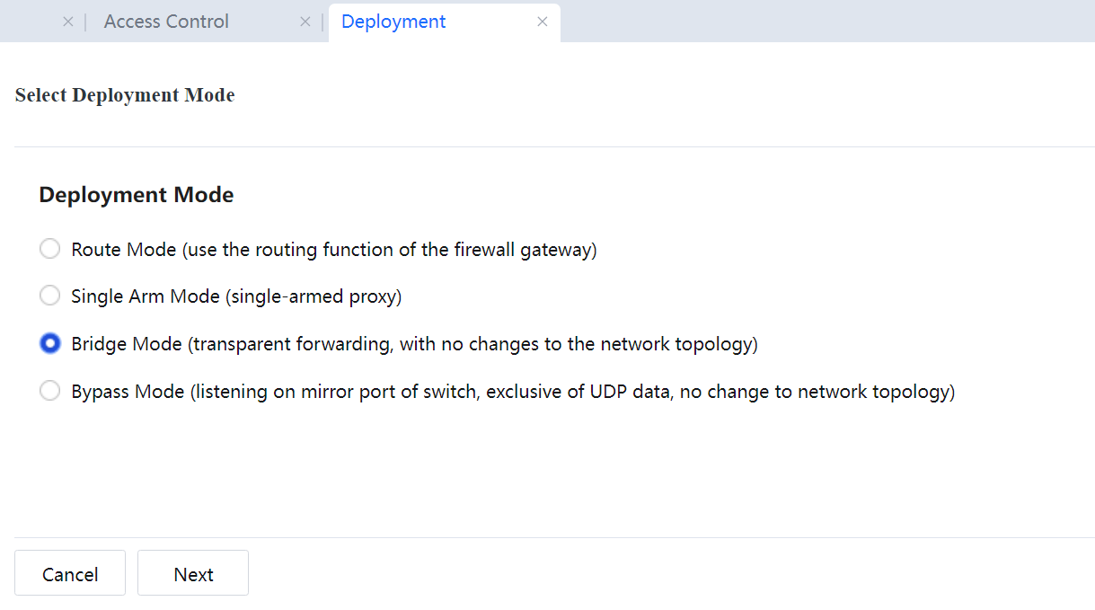
In bridge mode, the device is considered a network line with a filtering function. This mode is usually enabled when the original network structure cannot be modified. Deploy the device between the original gateway and the intranet users. You only need to configure the device without modifying the configurations of the original network or intranet users. The device is invisible to the original network and intranet users, which is characteristic of the bridge mode.
Operating environment 1: The device functions as a bridge with one input and one output. 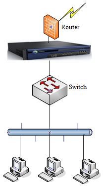
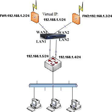
Operating environment 2: If Virtual Router Redundancy Protocol (VRRP) or Hot Standby Router Protocol (HSRP) is enabled on the intranet, the device can be deployed in multi-bridge mode to implement basic audit control functions without affecting Active-Standby handovers of the original firewalls. The following figure shows the two operating environments.
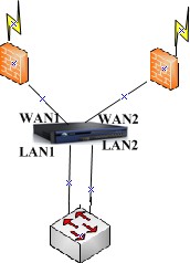
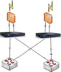
Example: VRRP is enabled between the two firewalls and the switch. The virtual IP address of the firewalls is 192.168.1.1. The device is deployed between the switch and firewall as a bridge with two inputs and two outputs.
The procedure is as follows:
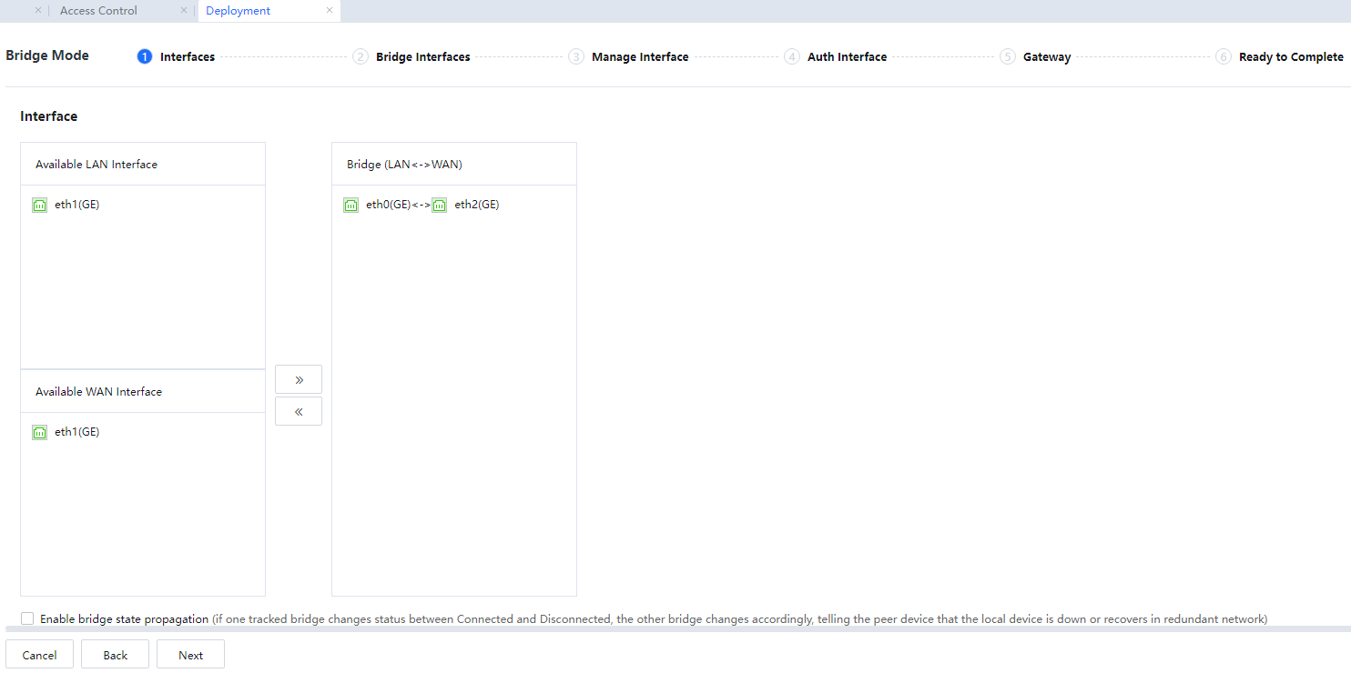
LAN Interface: Select an internal network interface from LAN Interface.
WAN Interfaces: Select a WAN interface from WAN Interface.
Bridge: Bridges are defined in Bridge. Data can be forwarded between interfaces on a bridge and cannot be forwarded between interfaces on different bridges.
If Enable bridge state propagation is selected, when a network interface on a bridge changes from connected to disconnected or disconnected to connected, the status of the other network interface changes accordingly. It ensures that the status of the two network interfaces on a bridge is synchronous. This function is to notify the peer device that the link is faulty or resumes normal in a redundancy environment. We recommend you select this item.
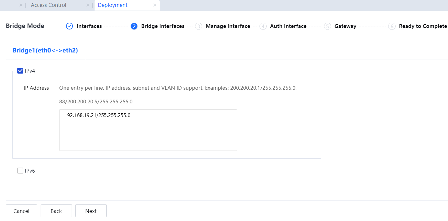
VLAN data passes through the device. Therefore, VLAN information needs to be configured, including the VLAN ID, VLAN IP address (an idle IP address is assigned to each VLAN), and VLAN mask.
![]()
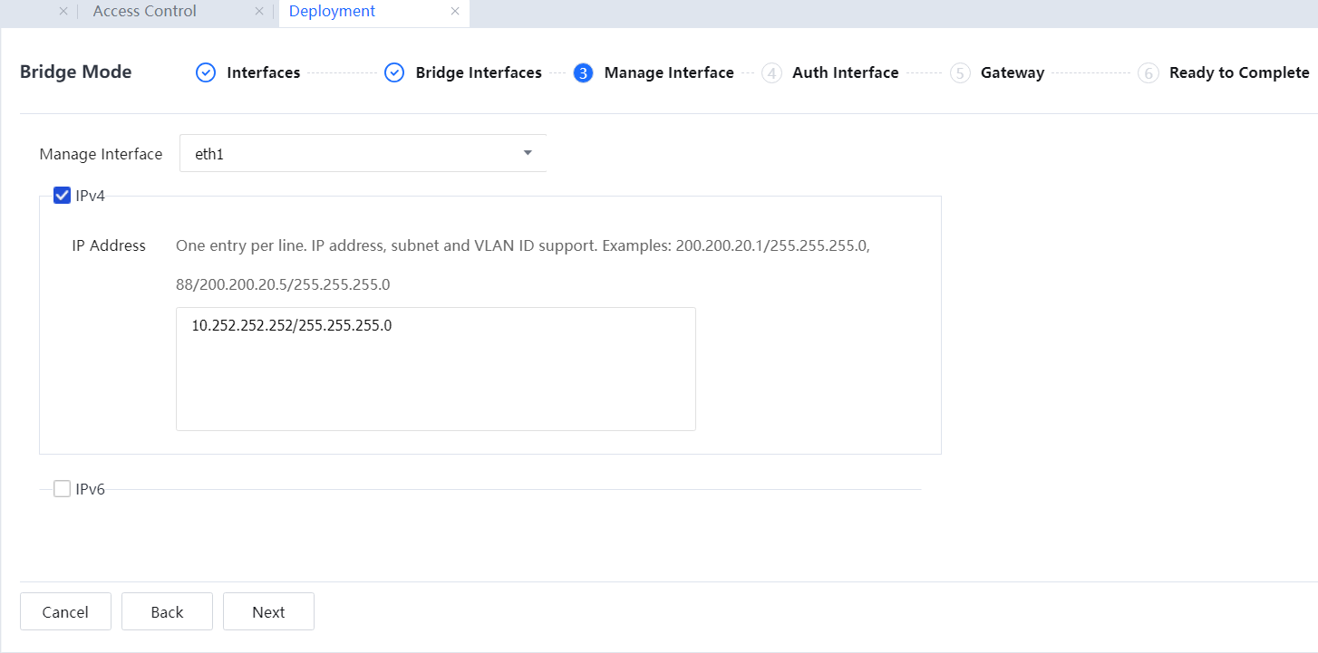
Network access data on the intranet will not be affected if no idle IP address is available. However, in this case, the device has no IP address for communication with the intranet and external network. Some functions, such as embedded library update, web authentication, and Ingress, will be affected. To solve this problem, connect the management interface to the intranet switch so the device can communicate with the intranet and external network. The following will describe the configuration in detail.
The bridge IP address can be empty when the device operates in bridge mode. The bridge IP addresses must be on different network segments, and the VLAN IDs must be unique.
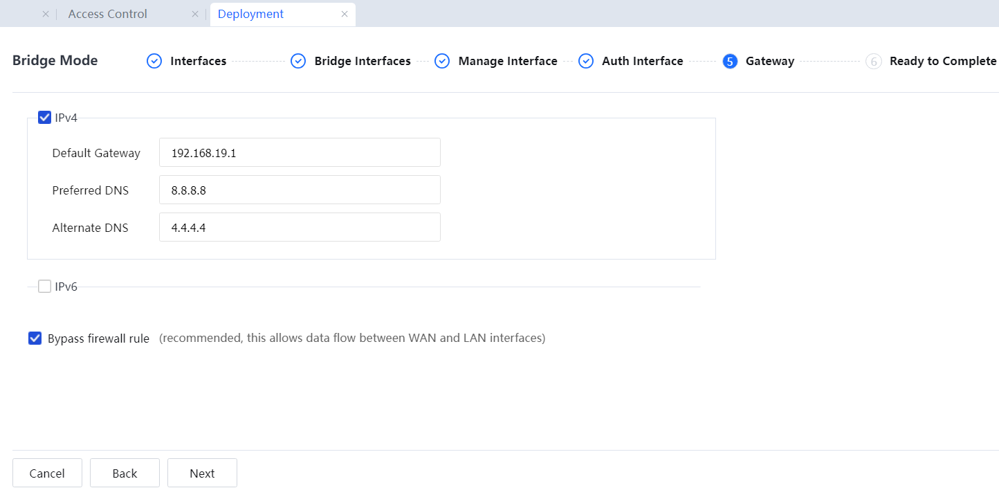
Set a public network IP address assigned by the carrier as the DNS address. Select Bypass firewall rule to enable the firewall rule that allows all data between the WAN and the LAN.
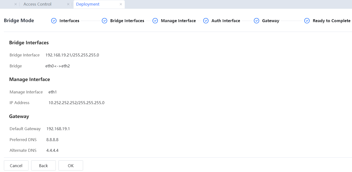
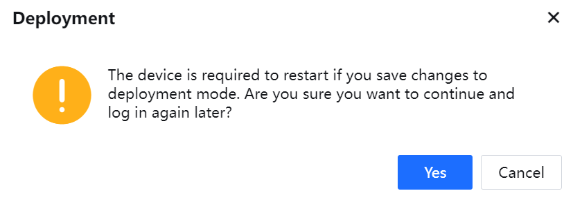
Restart the device for the configurations to take effect. In the displayed dialog box asking for your confirmation, click Yes.
![]()
1. When the device operates in bridge mode, the gateway addresses of all PCs on the LAN do not need to be modified. Retain the internal interface IP address that points to the front-end device.
2. During data penetration, ensure that the WAN connects to the front-end router and the LAN connects to the intranet switch. In this way, online behaviors can be monitored and controlled when data is transmitted from the LAN to the WAN.
3. The bridge mode is implemented at the data link layer (the second layer of the OSI model). Several network interfaces of the device are bridged. The data at the data link layer and above layers can be penetrated. The IP/MAC address binding function and DHCP function enabled on the original gateway can be implemented to support the data penetration function at the data link layer.
4. The device does not provide the NAT function in bridge mode.
5. The VPN function of the device is unavailable in bridge mode.
6. To enable functions such as antivirus and mail filtering or to enable the device to automatically upgrade the URL Database and enable applications to identify the rule library and antivirus library, you need to configure the bridge IP address, default gateway, and DNS and ensure that the device can access the external network. To check whether the device can access the external network, upgrade the console and perform a ping test.
7. If functions that need to be redirected to the device are required, such as web authentication and Ingress. The intranet covers multiple network segments, enabling indirect routes to the network segments of the intranet to direct to the routing device of the network intranet.
8. In bridge mode, the device supports VLAN trunk penetration, and 802.1q-VLAN addresses can be configured as bridge IP addresses. In other words, the device can be connected to the VLAN trunk in transparent mode.

 {{ $t('index.defaultHeader.chromeBrowserTip') }}