{{ secondMenu.name }}


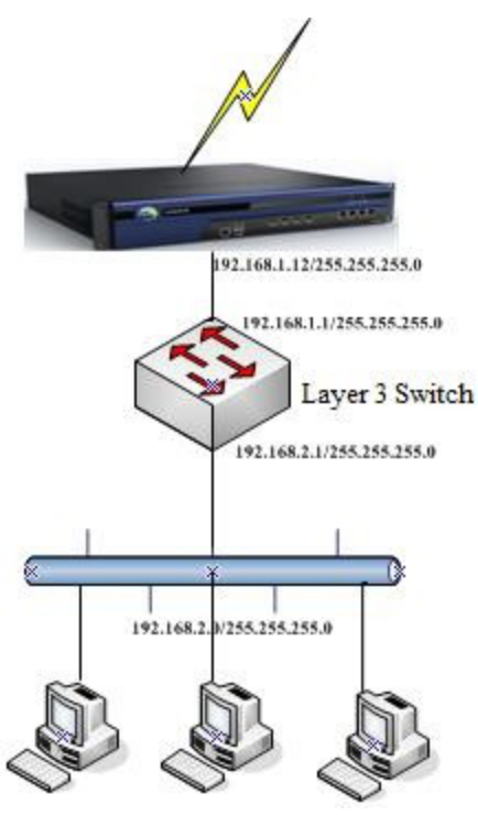
In route mode, the device functions as a router. The device is typically deployed at the egress of the intranet or behind a router to implement Internet access for the LAN. The following figure shows a typical deployment scenario. 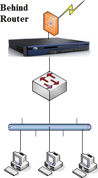
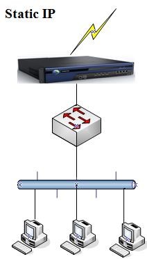
Example: The customer's network covers L3—the device functions as a gateway to implement Internet access for intranet users. A public network line (fiber) is available and assigned a fixed IP address.
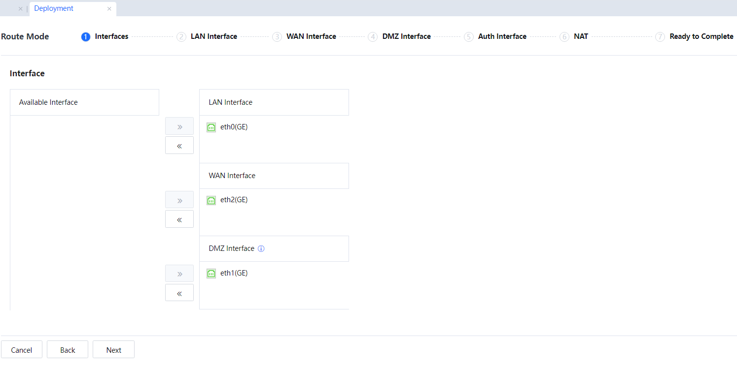
LAN interface list: A network interface added to the LAN interface list serves as an internal network interface and needs to be connected to the internal network.
WAN interface list: A network interface added to the WAN interface list serves as a WAN interface and needs to be connected to the external network. If multiple WAN interfaces are required, apply for multi-line authorization.
DMZ interface list: A network interface added to the DMZ interface list serves as an internal network interface. Important servers can be connected to the DMZ, and the firewall settings on the device can restrict the access of intranet users, thereby ensuring the security of the servers.
The default LAN interface is eth0, the default DMZ interface is eth1, and the default WAN interface is eth2. It is recommended that the positions of these network interfaces not be modified and conform to the device panel.
Other idle network interfaces can be added to any interface list.
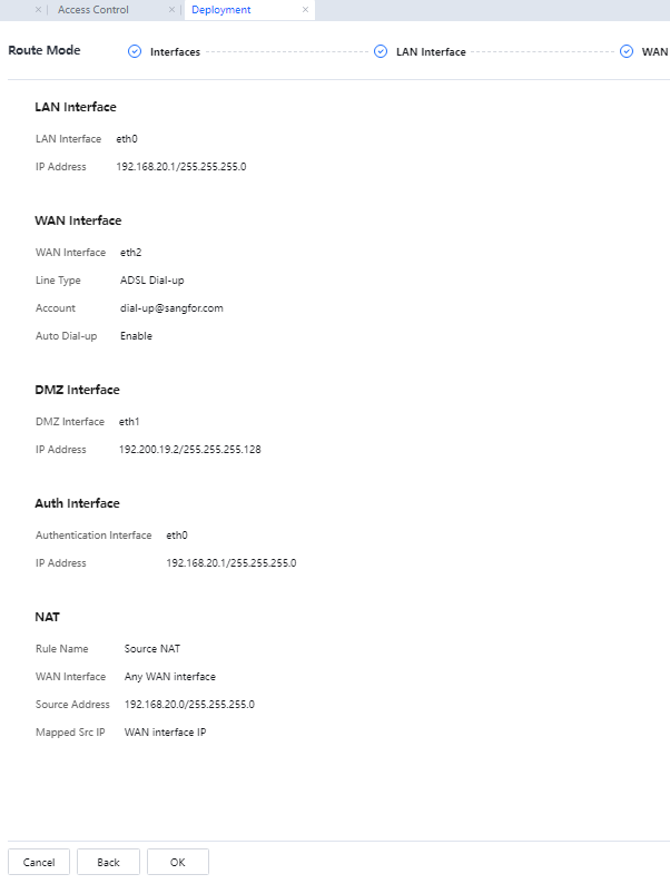
In this example, set the IP address of LAN interface eth0 to 192.168.20.1/255.255.255.0.
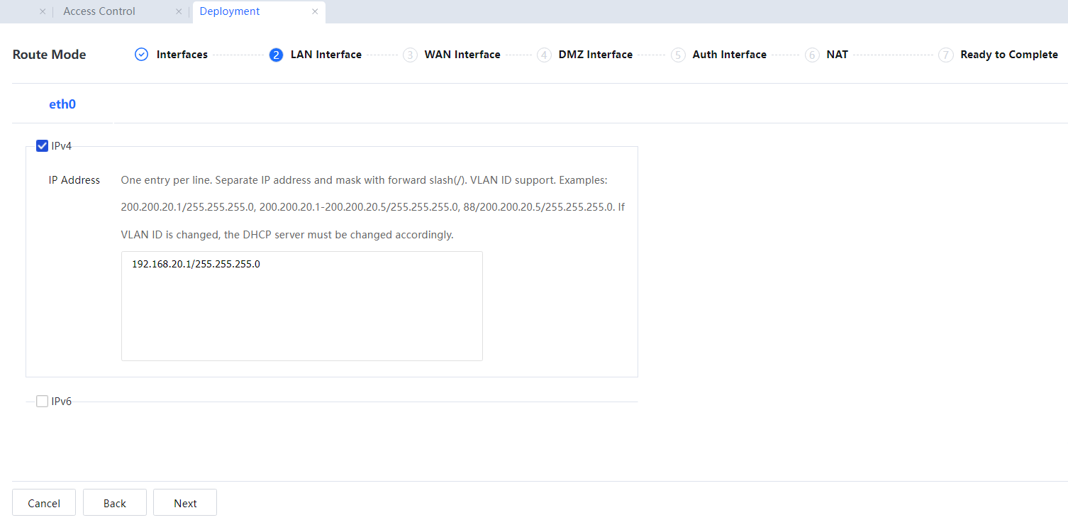
![]()
The current IAG version is compatible with IPv6. Therefore, IPv6 addresses can be configured for the network interfaces, gateway, and DNS. The following is an example of configuring IPv4 addresses.
If virtual local area networks (VLANs) are divided on the switch, and the LAN interface of the device is a trunk interface, VLAN needs to be enabled. In this example, an L3 switch is used, and therefore VLAN does not need to be enabled.
In IP Address, enter the ID and IP address of each VLAN. The IP address assigned to a VLAN must be idle. If VLAN 2 exists and resides on network segment 10.10.0.0/255.255.0.0, and the IP address
10.10.0.1 is not used on the intranet, 2/10.10.0.1/255.255.0.0 can be entered in the IP address list. Add information about other VLANs one by one on different rows.
The WAN interface supports Auto assigned, Specified, and PPPoE modes. In this example, the public network line is an optical fiber and assigned a fixed public network IP address. Therefore, select Specified.
If the public network IP address is automatically obtained over DHCP, select Auto assign. In this example, the public network IP address has been assigned. Therefore, enter the assigned public network IP address, gateway address, and DNS address.
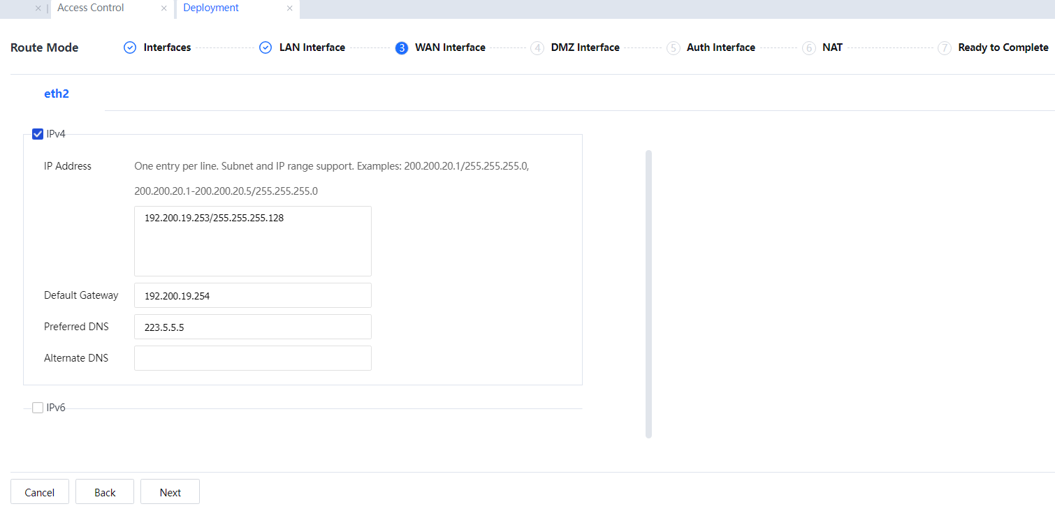
![]()
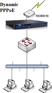
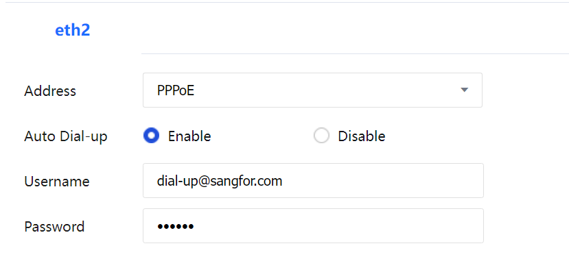
If PPPoE is employed, connect the WAN interface to a modem. If Enable is selected in Auto Dial-up, automatic dialup will be performed after the connection line is disconnected abnormally or the device is restarted. Enter the dialup account and password.
A proxy rule is added in NAT on the page displayed after choosing System > Firewall > IPv4 SNAT. The rule name and IP address to which a source address is translated cannot be modified here. They can be modified on the IPv4 SNAT page. If Internet access needs to be achieved for users on another network segment through a proxy, add another IPv4 SNAT rule on IPv4 SNAT. 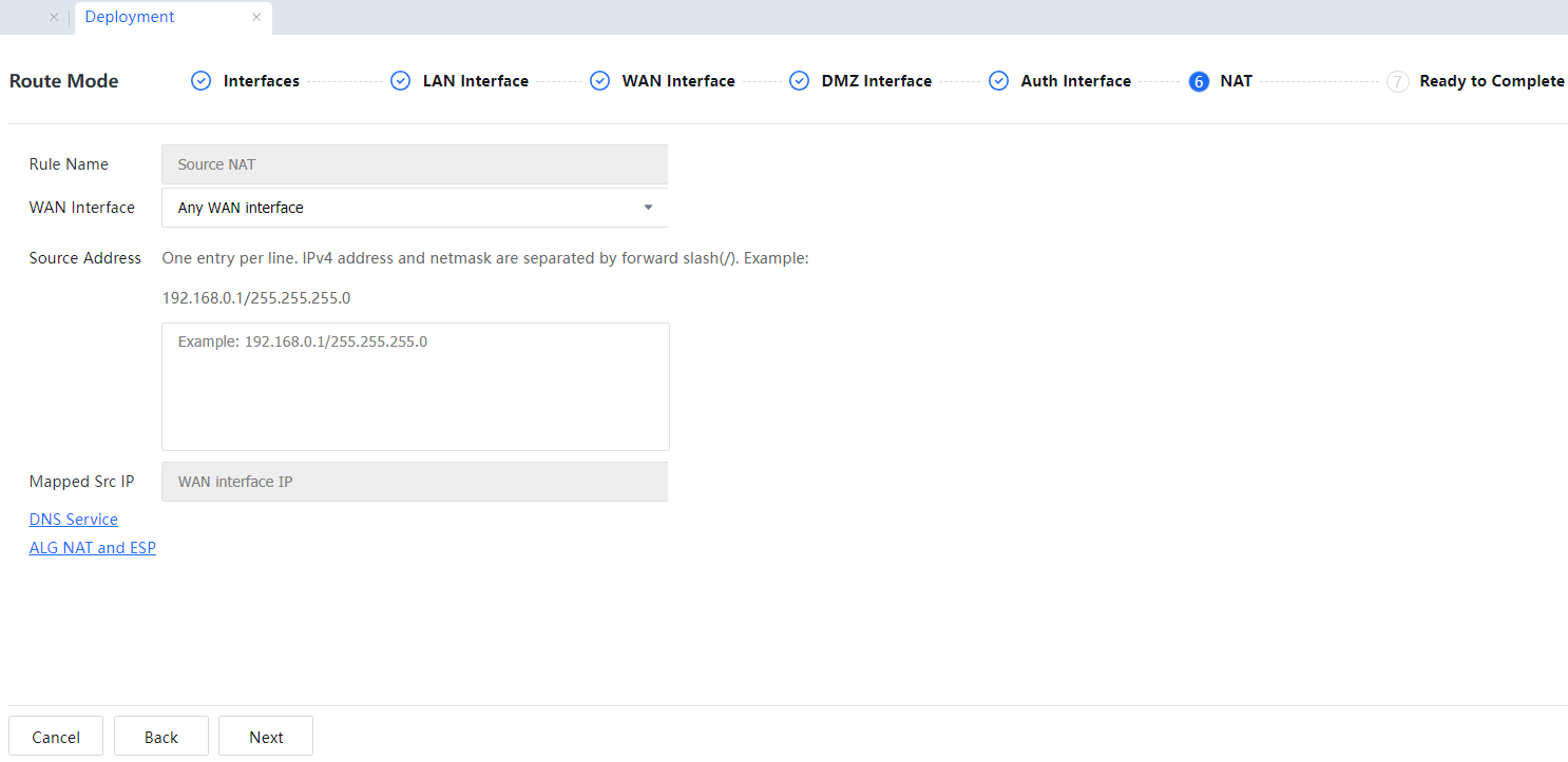
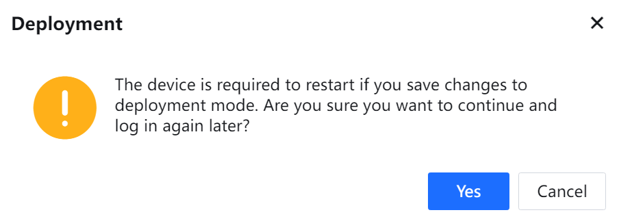
Restart the device for the configurations to take effect. Click Yes in the dialog box that asks for your confirmation.
![]()
1. When the device operates in route mode, the gateway addresses of all PCs on the LAN point to the IP address of the device’s LAN interface or the L3 switch, and the gateway address points to the device. The device performs NAT for Internet access data or forwards the data.
2. The IP addresses of the WAN, LAN, and DMZ interfaces must be on different network segments.
3. After an 802.1q-VLAN address is configured for the LAN interface. The LAN interface can connect to the trunk interface of an L2 switch that supports VLAN. The device (one-armed router) can then forward data among VLANs and implement firewall rules between LANs. The device can implement
4. Access control between different VLANs.
5. If the route mode is set to asymmetric digital subscriber line (ADSL) dialup, select PPPoE when setting the IP address of the WAN interface in step 5 and fill in the dialup account and password. Other operations are the same.
6. If a front-end device is configured, set the IP address of the WAN interface to be on the same network segment as the IP address of the LAN interface of the front-end device. Other operations are the same.
7. If DHCP is enabled on the front-end device, configure the WAN interface to automatically obtain an IP address and ensure normal communication between the WAN interface and the DHCP server.

 {{ $t('index.defaultHeader.chromeBrowserTip') }}