{{ secondMenu.name }}


Endpoint Visibility is to view the current internal network equipment status and IP usage status. The module includes the following features: Endpoints, IP Ranges, and Endpoint Discovery.
3.3.1.2.1.1 Checking Endpoints
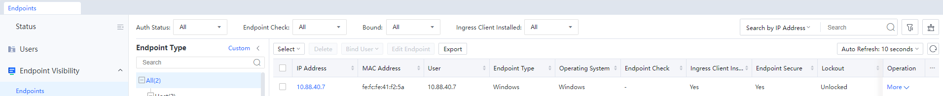
Endpoints is to view the status of internal network equipment. When the endpoint scan function is not enabled, the interface is as follows:
After enabling and configuring the endpoint scanning function, the interface is as follows:
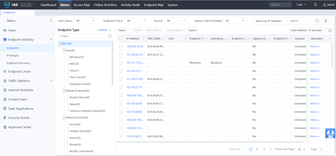
Here you can see all the internal network endpoint IP addresses, MAC addresses, users, groups, endpoint devices, operating systems, first detected time, last login time, and operations.
Click the IP to view endpoint details, and you can see the detailed information of the endpoint as follows:
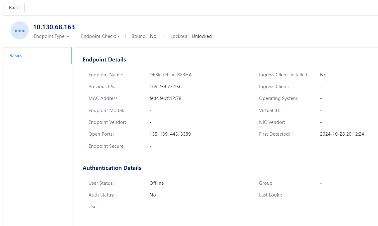
Basic information: including endpoint type, user, group, IP/MAC address information, vendor, operating system, first detected time, last login time, open ports, etc.
Status: Online refers to whether the endpoint has the same IP in the online user list. The presence of the IP indicates that the user has used the endpoint to go online. At the same time, it will display the user's information and the group's status. Offline means that the endpoint IP is currently not used by users.
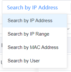
In the upper-right corner of the Endpoints page, enter a keyword in the search box to search for endpoints and query the corresponding endpoint statuses by IP address, IP range, MAC address, or user.
Search by IP address, Search by MAC address, and Search by username can be used to search for the specified endpoint in Status > Endpoint Visibility > Endpoints.[A5][6] The interface is as follows:
3.3.1.2.1.2 Filtering Endpoints
Click the Filter to set the specified condition to view the corresponding endpoint. The interface is as follows:
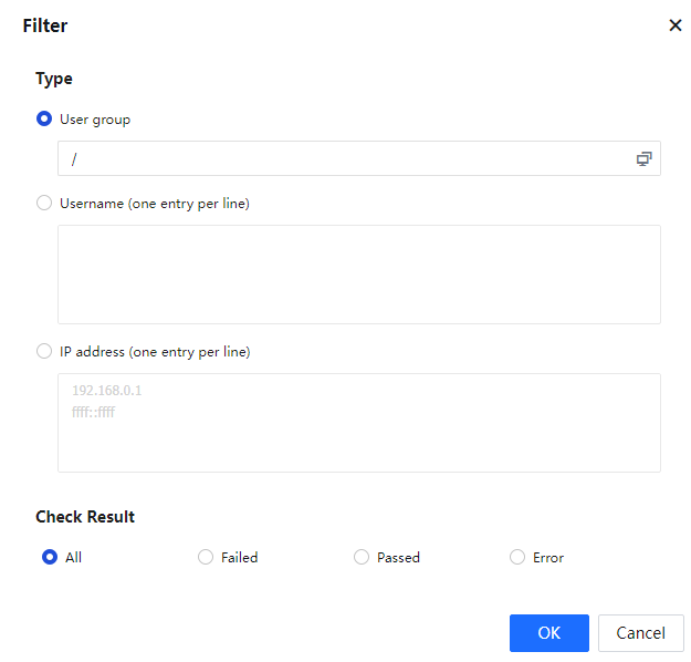
First Detected can choose a built-in time range, including all, the last day, the last seven days, the last 30 days, or a custom time range.
Status can choose All, Online, and Offline.
After selecting Object, you can filter according to Username or IP address, enter the specified user and IP, and click OK.
3.3.1.2.1.3 IP Ranges
IP Ranges is to view the live IP status of the intranet, as shown in the figure below: 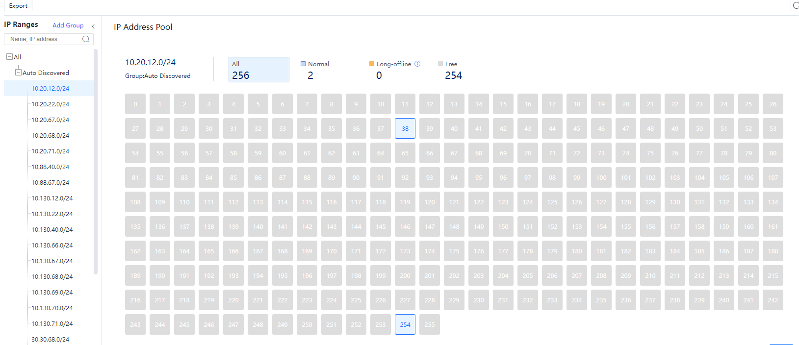
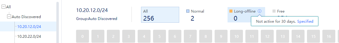
IP Ranges display the 24-bit address segment where the surviving IP address of the intranet is located, with a maximum of 1024 C segments.
The specific IP survival status in the segment is displayed on the right, and the following figure will be displayed when the mouse hovers on a particular IP:
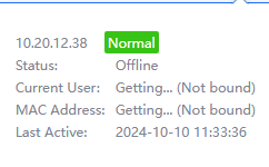
Normal: Indicates that this IP has been scanned alive within a period (the default is 30 days, configurable). Online refers to whether the endpoint’s IP is in the online user list. If there is, it means the user has used the endpoint to go online, and it will display the user and group information at the same time.
Free: Indicates that this IP has not been scanned alive.
Long-offline: Indicates that this IP has been scanned alive before, but after a certain period (the default is 30 days, configurable, specify the time for long-offline status through the small “i” icon as shown in the figure below) the IP did not scan to be alive, and it will be defined as offline.
3.3.1.2.1.4 Endpoint Discovery
Endpoint Scan is to enable and set the entire network endpoint scan function, as shown in the following figure.
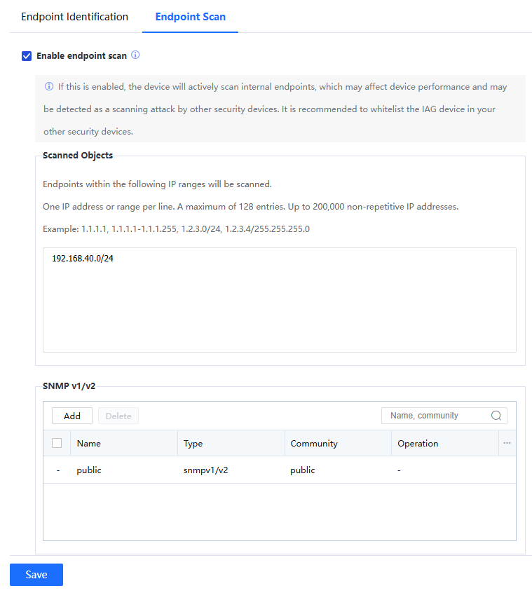
The endpoint list will show the endpoint status only after you select the Enable endpoint scan.
Scanned Objects: Endpoints within the following IP ranges will be scanned.
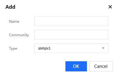
SNMP v1/v2: You need to configure SNMP and configure the corresponding name and community name for network equipment. The type can be v1 or v2 protocol, as shown in the figure:
MAC Address Acquisition: Two methods can be used to obtain the MAC address in the Layer-3 environment. The setting methods are as follows:
Method 1: Obtain the MAC address of intranet users through mirroring (recommended)
Select MAC address is acquired from captured ARP packets or DHCP packets, connect any free network port of IAG to the switch, enable mirroring on the corresponding interface of the switch, and mirror related data packets to the IAG. This method does not require the switch to enable the SNMP protocol.
Method 2: configure to acquire MAC across layer three
Intranet users are bound to the MAC address or limited to the user's MAC address range, and the intranet is a three-layer environment. Therefore, you need to enable the MAC acquisition across L3 function to obtain the MAC address of the intranet user. To use this function, make sure that the intranet switch supports the SNMP. This way, the IAG device can obtain the real MAC addresses of intranet users on the switch through the SNMP protocol.
Principle: The device will periodically send the SNMP request to the Layer 3 switch to request the MAC table of the switch and save it in the device memory. Currently, if computers in other network segments of the Layer 3 switch go online through the device, for example, a PC 192.168.1.2 (not the same network segment as the LAN port) goes online through the device. The PC data packet passes through the device, and the device verifies this data packet is the MAC address of the layer three switch and will not process this MAC address. The actual MAC address is searched in the memory according to the IP address 192.168.1.2 to verify the user's real MAC.
Step 1.Enable the SNMP function on the Layer 3 switch.
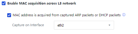
Step 2.Click to enter Access Mgt > Correlation Connection > MAC Address Acquisition to set and check Enable MAC acquisition across the L3 network on the device interface:
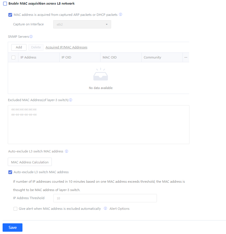
Step 3.Set SNMP Servers to add the information of the Layer 3 switch that needs to obtain the MAC address:
The Layer 3 switch first needs to enable the SNMP function.
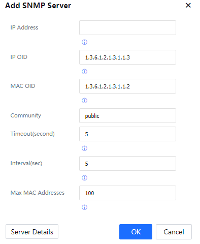
IP: Fill in the IP address of the switch.
IP OID: Fill in the OID corresponding to the IP in the SNMP information.
MAC OID: Fill in the OID corresponding to the MAC in the SNMP information.
Community: Fill in the SNMP negotiated key.
Timeout: Set the timeout period for IAG to obtain SNMP information.
Interval: Set how often the IAG sends SNMP requests to obtain information.
Max MAC Addresses: Set the maximum number of SNMP entries obtained each time.
Click Server Details to view the SNMP information on the SNMP server (the switch).
Click OK to complete the setting.
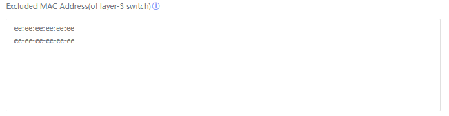
Step 4.Fill in the MAC address of the internal network switch to prevent this part of the MAC from being bound by the user, as shown in the figure:
Step 5.In addition to manually filling in the MAC address of the switch in the previous step, the device can also automatically discover the MAC address of the Layer 3 switch. The principle is: to count the number of IP addresses corresponding to the MAC every 10 minutes. If it is the MAC of a layer three switch, one MAC will correspond to multiple IP addresses.
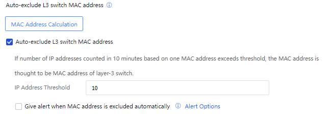
Click MAC Address Calculation to view the statistical results of each MAC.
Select Automatically exclude L3 switch MAC address. The device will automatically add MAC addresses that exceed the number of IP records to the MAC address exclusion list according to the set IP address Threshold.
Select Give alert when MAC address is excluded automatically to send alarm emails to the administrator after MAC is automatically added. The alert options are set in System > General > Alert options.

 {{ $t('index.defaultHeader.chromeBrowserTip') }}