{{ secondMenu.name }}


For an IAG working in the bridge mode, all the data is transferred through the IAG using the same line, regardless of the number of lines connected to the front-end device and the number of egresses of the device in multi-bridge mode. By default, the IAG performs traffic control over all the lines. Virtual lines are required if multiple lines must be controlled separately in bridge mode.
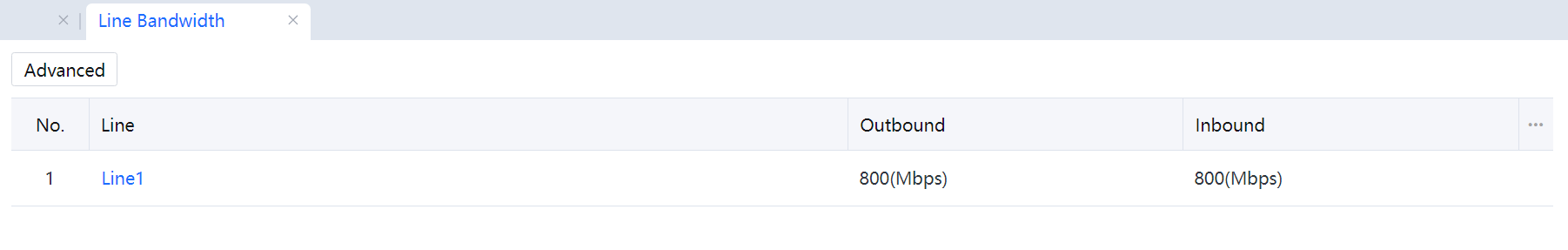
As shown in the following figure, there is only one default virtual line: line 1. If no other line is configured, line 1 must be the total bandwidth of all the physical lines if multiple Internet lines connected to the front-end device or the local device are configured with various egresses in multi-bridge mode. However, in this case, the IAG cannot control the traffic of multiple Internet lines separately.
Scenario
The IAG is deployed in bridge mode, as shown in the following figure. The firewall has two egresses, including one 10 Mbps line from China Telecom and one 10 Mbps line from China Unicom. The P2P traffic of the lines must be controlled separately so that the P2P traffic of each line does not exceed 20% of the bandwidth.
Configuration Steps
Step 1.Configure two virtual lines on the IAG, each corresponding to an Internet line of the firewall. Set the bandwidth of the virtual lines separately based on the actual bandwidth of the corresponding Internet lines.
Go to Bandwidth Management > Line Bandwidth, click Line 1, and set the bandwidth value of the line.
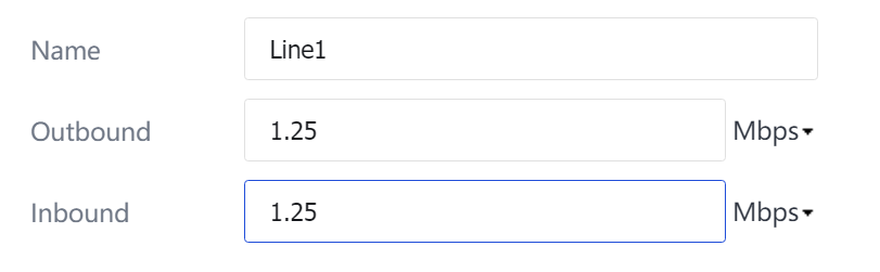
Assume that line 1 in this example corresponds to the line from China Telecom. The following figure shows the configuration for line 1.
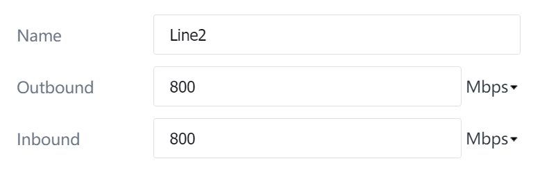
Go to Bandwidth Management > Line Bandwidth, click Add, and set the bandwidth value of line 2. Assume that line 2 in this example corresponds to the line from China Unicom. The following figure shows the configuration for line 2.
Step 2.Configure virtual line rules.
The rules help distribute data between the virtual lines and correspond the virtual lines with the physical lines. Generally, the front-end device has route selection rules. You can copy the route settings of the front-end device to the virtual line rules. Refer to the firewall route selection settings shown in the following figure and set the virtual line rules.
Go to Bandwidth Management > Line Bandwidth > Virtual Lines > Virtual Line Rule and click Add[A122]. In the Edit Virtual Line Rule dialog box, select virtual line 1 for the data transferred to the IP addresses 202.96.0.0/24 through the line from China Telecom.
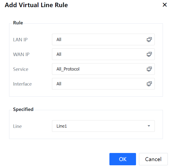
LAN IP: To set the source IP addresses of packets.
WAN IP: To set the destination IP addresses of packets.
Service: To set the protocol of packets.
Interface: It is used in the multi-bridge mode to specify the interface that forwards packets to the virtual line.
Line under Specified: To specify the virtual line destination of the data that meets the preceding criteria.
Step 3.Set rules for the other virtual lines until the virtual line rules are the same as the line rules of the firewall.
Step 4.Control the P2P traffic of the two virtual lines separately.
Navigate to Bandwidth Management > Bandwidth Channel and set the limited BM channel policy of line 1.
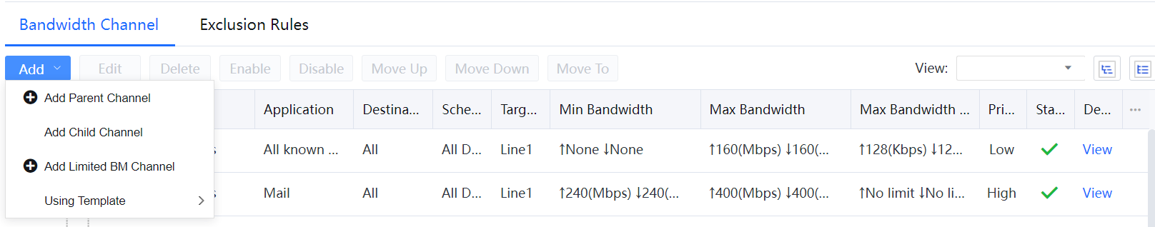
Click Add and select Add Parent Channel on the Bandwidth Channel tab.
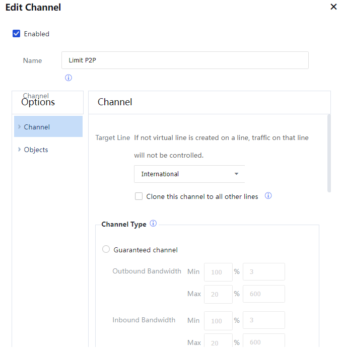
Set Target Line to Line 1.
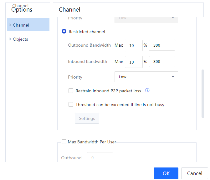
Channel Type: Outbound Bandwidth and Inbound Bandwidth to 20% of the total bandwidth each. The total bandwidth is 10 Mbps; therefore, the limited bandwidth is 2 Mbps.
Max Bandwidth Per User: It specifies how bandwidth is allocated among the channel users. The default option is Even, meaning the bandwidth is allocated evenly among the users.
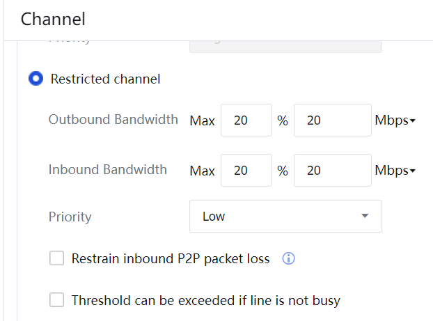
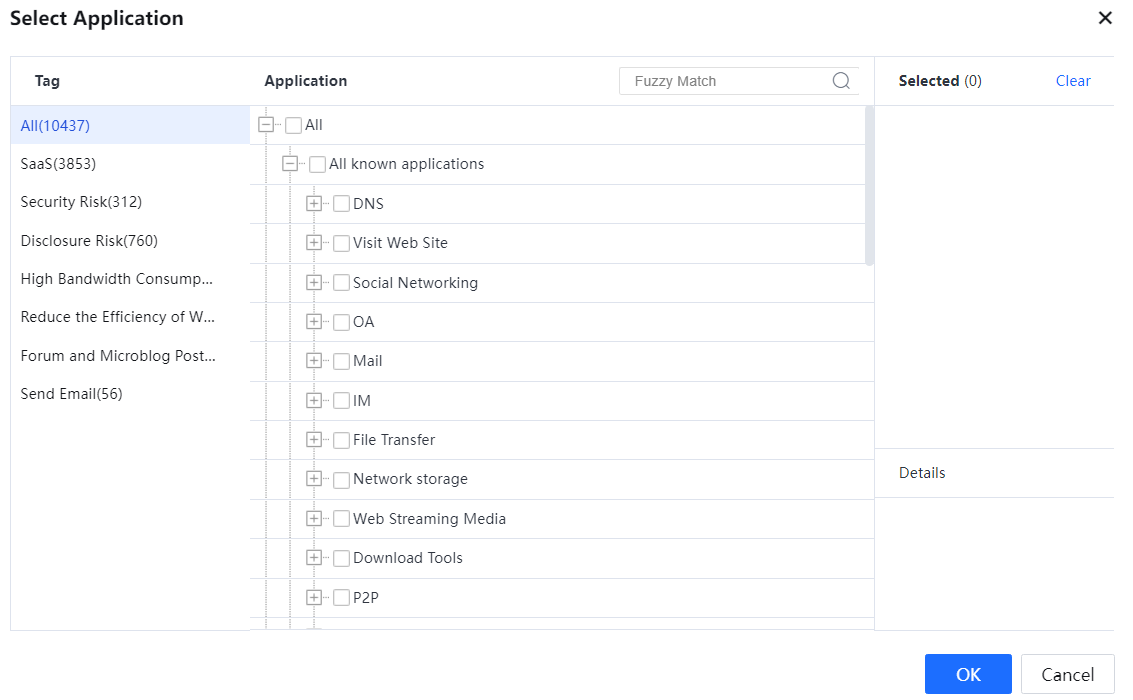
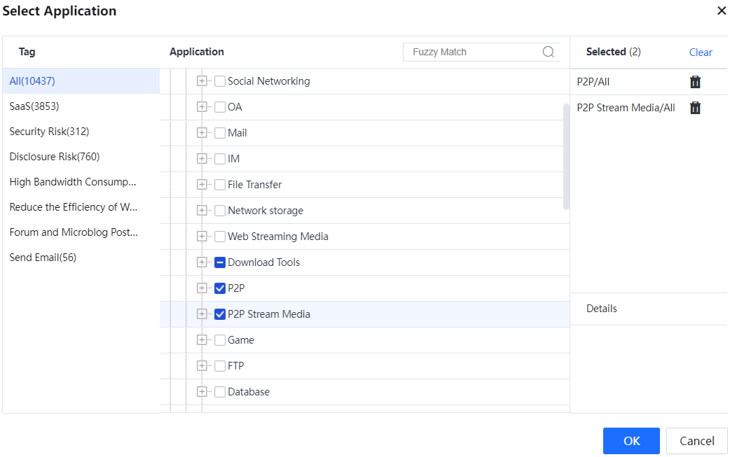
Channel Availability: Specifies the application types to which the channel is available. Click Select and select the application types in the User-Defined Applicable Service and Application dialog box that appears. In this example, select P2P/All and P2P Streaming Media/All to implement P2P traffic control. Click OK.
Object: It specifies the users, user groups, and IP addresses to which the channel is effective. If you select All Users, it is effective for all intranet users. After selecting applicable objects, click OK.
Step 5.Control the P2P traffic of the two virtual lines separately.
Use the method for setting the limitation channel policy of line 1 to set the limitation channel policy of line 2.
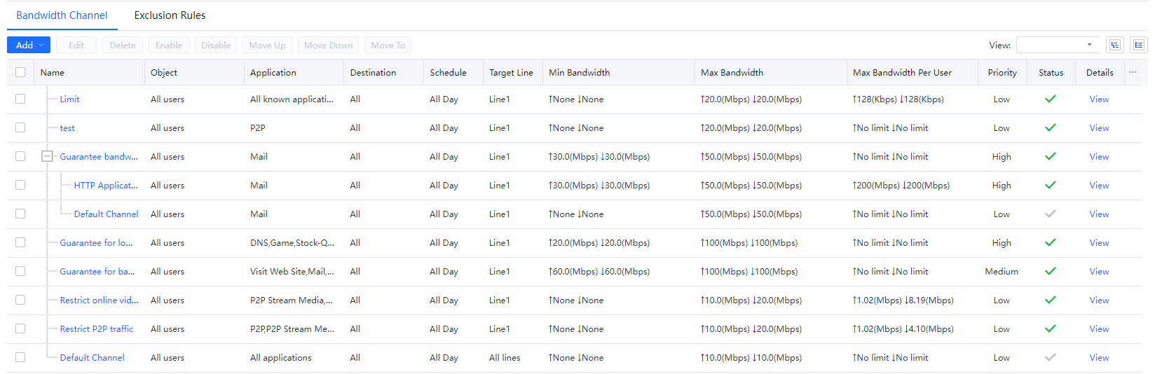
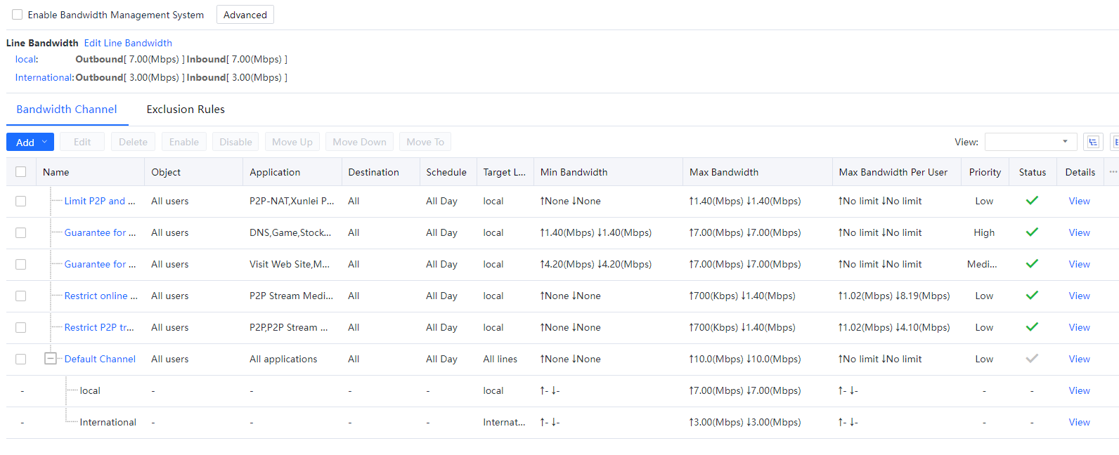
Step 6.The Bandwidth Channel tab page displays the configured channels. The limitation channel configuration is complete.
Example: The device serves as a bridge, and the firewall has two ports covering the international and local lines. The policy-based routing enables international line traffic to go through the international line with the bandwidth of 3 Mbit/s and local line traffic to go through the local line with 7 Mbit/s. It is required that P2P data going through the two lines are subject to traffic control so that respective bandwidths of P2P data occupied on the two lines do not exceed 10%, and the region is China.
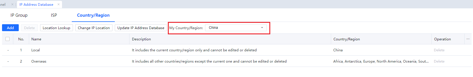
Step 1.Make sure that the region identified in Country/Region is correct.
Step 2.Configure virtual lines.
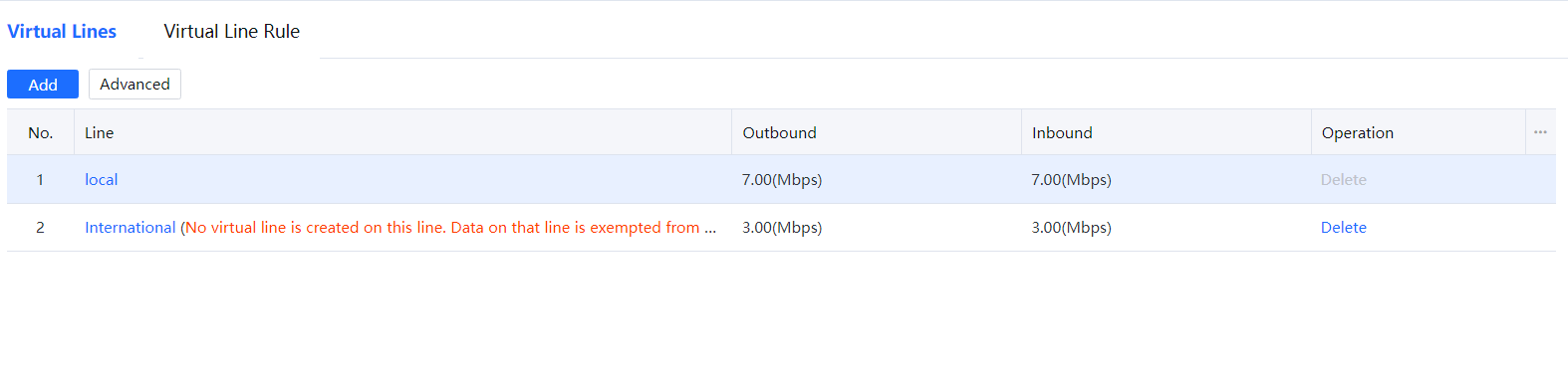
Choose Bandwidth Management > Virtual Lines and create an International virtual line with an outbound and inbound rate of 3Mbps, and a Local virtual line, with an outbound and inbound rate of 7Mbps.
Step 3.Configure virtual line rules.
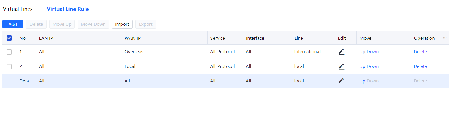
Choose Bandwidth Management > Virtual Line Rule and create two virtual line rules. One of the WAN IP’s rules selects Overseas to specify the international line, and the other selects Local to specify the local line.
Step 4.Configure traffic control.
Choose Bandwidth Management > Channel > Enable the traffic control switch to create a new channel. Select International as the target line, and set the limited bandwidth.
Bandwidth Usage Range: To set what types of data will be matched to this channel, i.e., the usage range of the channel. Click Select custom application, and select application type in the Custom Applicable Services and Applications pop-up box. In this example, P2P-related data needs to be subject to traffic control, and applications, including P2P, and P2P Steam Media should be selected. Click OK to complete the settings of applicable applications.
Objects: To set users, user groups, and IP addresses to which this channel is effective; checking All indicates that the channel is effective to all LAN users; after selecting the Objects, click OK to complete the settings.
Step 5.Perform traffic control on application data of P2P on two virtual lines.
Set the limited channel policy of line 2 (local line) using a method similar to that in the international line, which is not repeated here.
Step 6.After the settings are completed, set channels will be displayed in the Bandwidth Channel, indicating that the configuration of the limited channel is complete.
![]()
1. Virtual line rules are matched from top to bottom.
2. Virtual line rules can be configured in batches to select lines based on destination IP addresses and bridges. On the Virtual Line Rules page, click Batch Import and set rules.
3. Virtual Line Rules can be imported and exported.

 {{ $t('index.defaultHeader.chromeBrowserTip') }}