{{ secondMenu.name }}


Connect the power cable to the power interface on the rear panel of the IAG device and switch on the power supply. The POWER indicator (green) and ALARM indicator (red) on the front panel will light up. The ALARM indicator will go out one or two minutes later, indicating the device runs normally.
Follow the instructions below to wire the interfaces:
• Use a standard RJ-45 Ethernet cable to connect the LAN interface to the LAN and then configure the IAG device.
• Use a standard RJ-45 Ethernet cable to connect the WAN1 interface to a network access device, such as a router, optical fiber transceiver, ADSL Modem, etc.
• Use a standard RJ-45 Ethernet cable to connect the DMZ interface to the DMZ network. Generally, the web server and mail server providing services to a wide area network (WAN) are deployed in the DMZ zone. The IAG device provides secure protection for these servers.
When wiring the interfaces, please use the correct cables for connection as instructed below:
• Use the straight-through cable to connect a WAN interface with the Modem and a crossover cable to connect a WAN interface with the router.
• Use the straight-through cable to connect the LAN interface with the switch and a crossover cable to connect the LAN interface on the device with the network interface on the computer.
If the connections cannot be established while the corresponding indicator functions normally, please check whether the cables for connections are correct. The differences between straight-through cable and crossover cable are the wire sequences at both ends, as shown in the following figure.
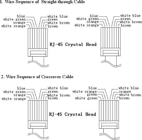
Wire Sequences of Straight-through Cable and Crossover Cable
After correct connections, log in to the console of the IAG device and configure the deployment mode according to the network topology’s requirement.
![]()

 {{ $t('index.defaultHeader.chromeBrowserTip') }}