


{{ secondMenu.name }}




In the active/active Layer 2 deployment, the two Network Secure devices are deployed as bridges within the network (the bridge mode includes the Layer 2 mode and the virtual wire mode). Both devices are active for handling traffic forwarded to them, and their settings and sessions are synchronized through the heartbeat interface.
9.7.6.3.1.1Configuration Case
An enterprise plans to deploy two Network Secure devices to its LAN in the virtual wire mode. The LAN implements link aggregation based on routers and core switches, and the two Network Secure devices should be deployed as bridges in the active/active mode. As the request and response packets passing through the two devices may be transmitted using different paths, link aggregation is required. The network topology is shown in the following figure.

Prerequisites
Configuration Procedures
Step 1.Configure the heartbeat interface for the active controller. Go to Network > Interfaces > Physical Interfaces to configure an IP address for the eth1 interface. In this case, the IP address is set to 11.1.1.1/24, as shown in the following figure.

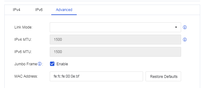
Step 2.Configure the data synchronization interface for the active controller. Go to Network > Interfaces > Physical Interfaces to configure an IP address for the eth4 interface. In this case, the IP address is set to 12.1.1.1/24. Enable Jumbo Frame on the Advanced tab, as shown in the following figure.
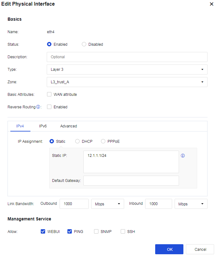

Step 3.Configure link state propagation for the active controller. Go to Network > Interfaces > Link State Propagation, select Enable link state propagation and click Add. Select eth2 and eth3, as shown in the following figure.

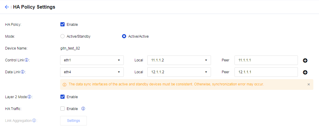
Step 4.Enable the HA policy and select the Active/Active mode for the active controller. Go to System > High Availability and click Settings. On the HA Policy Settings page, check Enable for HA Policy and select Active/Active as the Mode. Select eth1 as the Control Link interface and set the peer device's IP address to 11.1.1.2. Select eth4 as the Data Link interface and set the peer device's IP address to 12.1.1.2. Enable Layer 2 Mode, as shown in the following figure.

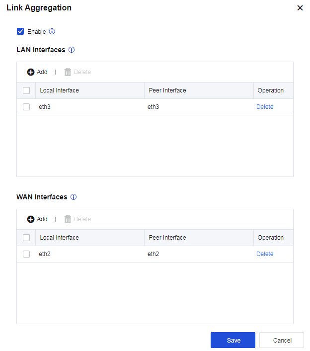
Step 5.Configure link aggregation for the active controller. On the HA Policy Settings page, click Settings next to the Link Aggregation field to enter the Link Aggregation dialog box. Add eth3 in LAN Interfaces and add eth2 in WAN Interfaces, as shown in the following figure. Click Save to proceed and the settings meet the conditions for enabling link aggregation.

Step 6.Assign the active role to the active controller. Go to System > High Availability > Sync Options and click Settings next to the Current Device Role field. Select Active, as shown in the following figure.

Step 7.Click the Save button to save the configuration.
Step 8.Configure the heartbeat interface for the passive controller. Go to Network > Interfaces > Physical Interfaces to configure an IP address for the eth1 interface. In this case, the IP address is set to 11.1.1.2/24, as shown in the following figure.

Step 9.Configure the data synchronization interface for the passive controller. Go to Network > Interfaces > Physical Interfaces to configure an IP address for the eth4 interface. In this case, the IP address is set to 12.1.1.1/24. Enable Jumbo Frame on the Advanced tab, as shown in the following figure.

Step 10.Enable the HA policy and select the Active/Active mode for the passive controller. Go to System > High Availability and click Settings. On the HA Policy Settings page, check Enable for HA Policy and select Active/Active as the Mode. Select eth1 as the Control Link interface and set the peer device's IP address to 11.1.1.1. Select eth4 as the Data Link interface and set the peer device's IP address to 12.1.1.1. Enable Layer 2 Mode, as shown in the following figure.
Step 11.Configure link aggregation for the passive controller. On the HA Policy Settings page, click Settings next to the Link Aggregation field to enter the Link Aggregation dialog box. Add eth3 in LAN Interfaces and add eth2 in WAN Interfaces, as shown in the following figure.
Step 12.Assign the passive role to the passive controller. Go to System > High Availability > Sync Options and click Settings next to the Current Device Role field. Select Passive, as shown in the following figure.


1. If you deploy Network Secure devices in the active/active Layer 2 mode in scenarios where the request and response packets are transmitted using different paths, link aggregation is required. If the next-hop IP or MAC addresses that Network Secure 1 and Network Secure 2 learned from the upstream and downstream devices are different (the upstream and downstream devices use different routing interfaces), link aggregation and HA traffic are all required.
2. Use LACP to aggregate links for the upstream and downstream devices. Change the default MAC-based forwarding algorithm to the IP-based forwarding algorithm for the aggregate interface. Otherwise, the forwarding performance of Network Secure may decrease due to possible asymmetric routing issues.
3. Enable Jumbo Frame for the corresponding data synchronization interface when link aggregation is used. One Network Secure device must add the Layer 2 header, Layer 3 header, Layer 4 header, HA header, and Zmode information to a packet before sending it to the other Network Secure device through the control link. In this case, the packet size may exceed the MTU, resulting in packet fragmentation and reassembly, as well as performance degradation. Enabling the Jumbo Frame can avoid such issues.


 {{ $t('index.defaultHeader.chromeBrowserTip') }}