{{ secondMenu.name }}


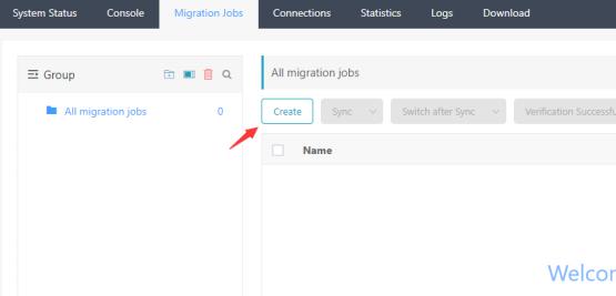
Step 1. Log in to the SCMP with the system admin account, navigate to Migration and click Create.
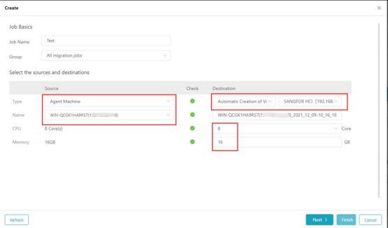
Step 2. Configure the basic information of the migration, select the Agent
Machine or Agentless Machine for the Source and select the virtual machine to be migrated. For the destination machine, select Automatic Creation of
Virtualization Data Center when the supported HCI has been added to
Virtualization Data Center. Otherwise, select Agent Machine for VM booted with bare metal restore medium.
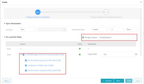
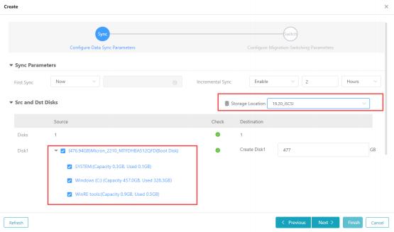
Step 3. Click Next to proceed with the disk information, and select the
Storage location information of the destination HCI environment. It is
required that the number of hard disks of the destination machine must not be less than the number of hard disks of the source machine, and the capacity of each hard disk of the destination machine must not be less than the source
machine.
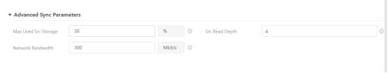
Step 4. Click Advanced Sync Parameters to configure the Max Used Src Storage, Network Bandwidth, and Src Read Depth for the migration task.
These parameters come with the default value, where you can change the configuration accordingly.
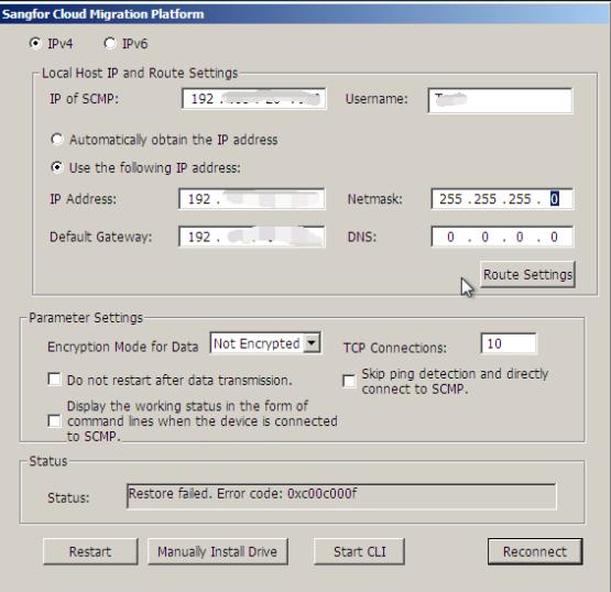
Step 5. Click Next to configure network configuration for migration: Currently only supports manual switching for migration. If the network information
needs to be modified while migrating, fill in the destination machine IP configuration, as shown below.
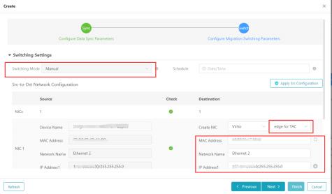
Step 6. In the above figure, an alarm appears in the DNS position because the DNS of the destination machine is configured with one line more than that of the source machine, which can be deleted manually or retained.
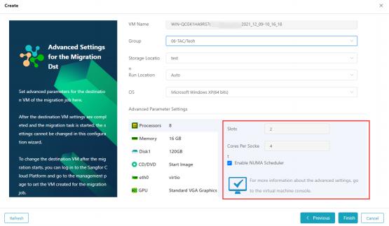
Step 7. Click Next to preview the configuration of the destination virtual
machine. Some VM configurations are editable, including Group, Processors, Memory, Disk, CD/DVD, NIC, and GPU.
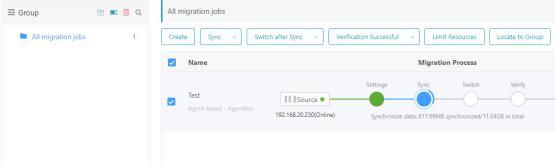
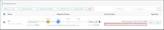
Step 8. Click Finish to save the configuration, and the migration task will start automatically. The process of this migration task can be traced under All
Migration Jobs. The synchronization completion time will be calculated after the configuration check is automatically completed.

Step 9. Navigate to the destination machine console to check the status. If it shows that the bare metal restores ISO obtains the address from DHCP, you need to manually configure the IP address that can access the migration
platform (and cannot conflict with the business machine address). The
configuration is completed before you can continue. Perform the migration.
Manual configuration can be avoided if a destination cluster is configured with DHCP or uses a static IP.
Step 10. The configuration is complete, and the data transmission action is started. If the synchronization times out, click the down arrow of the sync to restart complete synchronization.
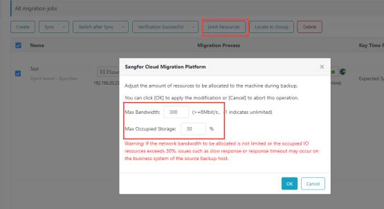
Step 11. During the data synchronization process, click allocated resources to configure or modify the migration QoS.
Step 12. To shorten the downtime, after waiting for the first full data to be completed and before the time allowed for downtime, click the button to perform an incremental synchronization.
Step 13. Within the time when the business is allowed to be interrupted, stop (do not shut down the source) the business(service), and then click [switch
after sync] to enter the switch option UI.
Step 14. Enter the switch option UI and select the operation when switching. Point-to-point migration scenarios recommend the user perform a
disconnection operation on the source end and automatically turn on the destination end virtual machine after the switch (as shown in the figure).
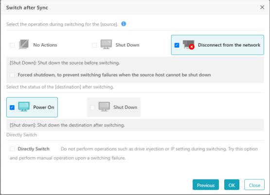
Step 15. Click OK to initiate the switching action.

Step 16. After the switch is completed, enter the verification state, enter the destination machine console at this time, and wait for the restart to enter the operating system.
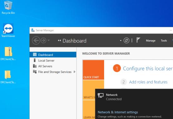
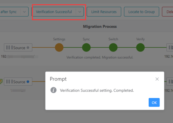
Step 17. After the handover is completed, confirm that the source end network is disconnected and enter the destination end for business verification. If the
verification is abnormal, perform abnormal troubleshooting or roll back
migration actions, shut down the destination virtual machine, and connect to the source machine to resume business. If the verification is normal, enter the migration management interface and click. If the operating system of the
source machine is a Linux system and the boot mode is UEFI boot, it may start abnormally after migration. To solve it, you can refer to the fault case UEFI
Linux virtual machine cannot enter the system.
Step 18. The migration is complete.

 {{ $t('index.defaultHeader.chromeBrowserTip') }}